I built a bunch of these with C31 because it seemed like the right thing to do, then did an experiment with a discrete IV which had its own LPF so I built a board without C31 etc. Then I put in op amps to compare, and noticed that I didn't notice the missing LPF. I added them on some boards I'm sending to friends but don't think I'd use them again on boards of my own.
If I can't hear the difference, one less component in the audio path seems like a win - see also Muntzing
If I can't hear the difference, one less component in the audio path seems like a win - see also Muntzing

It is imho the way to go indeed...experiments to find what suits best your system...tweaking is fun and having two pcb hence one for the reference is helping.
I've been trying to give it some time and develop an informed impression, BUT... it sounds fantastic! Wildly exceeds my expectations. Having DIY'd most of my other gear, I had convinced myself that DIY DAC would simply be too complicated for me, but Miro has done a great job making this DAC very straightforward to build. Anyways, because I thought I would never build my own DAC, I had gradually worked from a Soekris 1321 to a Denafrips Pontus II. I was quite sure that the Pontus would be my last DAC purchase, as I was blown away with the quality I was getting. That said, it was a lot more money that I wanted to spend on a piece of equipment, so when a set of free boards came my way for the Miro DAC, I thought I would give it a go with the slim chance it could displace my Pontus and allow me to recoup my money.
I'm about 5 hours in, and I'm convinced I can sell the Pontus 🙂 The Miro DAC really is fantastic and is every bit the equal of the discrete R2R Pontus. PLUS I get to play around with I/V and flavor to my preferences. Right now I'm preferring LM6171 to TL071, but those were simply the two opamps I had on hand.
Long story short, could not be more impressed with the sound quality I'm getting, and this is without really exploring I/V options, dialing in MSB, etc.
@codyt Well done 🤗
I am very happy to hear this 🤩 ... This DAC will gradually kill everything 🤣I'm about 5 hours in, and I'm convinced I can sell the Pontus.
The Miro DAC really is fantastic and is every bit the equal of the discrete R2R Pontus.
Very interesting - Pontus is non-budget Dac at all, I was lived with Ares a hole week but it's a simple middle-end device. I listen him in setup Lynx D78 with Piega premium 50 in audioshop and also in my home system. Compare him with my Akai 79 and Dac X6 on 4398.
Pontus and Miro1862 are different, and both really great. I certainly wouldn't take anything away from Pontus – its a superb sounding DAC. Ultimately I would be happy living with either DAC, but the flexibility of IV alone is reason enough to prefer the Miro DAC. Not to mention the cost difference and the satisfaction of building one's own equipment.
Got around to taking a couple FFT's this evening. I use a cheap Focusrite ADC to get these, so what you see should be taken with many grains of salt. In fact, disregard the noise – most of this can be attributed to the nearby equipment and dangling test leads. I'm typically measuring power amps or linestages with a signal generator, but here I used a WAV test tone and loopback from the Focusrite. I'm not quite sure the cause and effect of capturing these at different sample rates, how the test tone sample rate impacts measurements, etc. Mainly I just wanted to verify a successful build.
Double-checking the AD1862 datasheet, I was pleased with the overall THD. I have the DAC set to output 2v, and I imagine that's an important reference when looking at THD% for R2R DACs.
I did one measurement (002) with an ADC sample rate of 44.1khz, and the second (003) at 96khz. In 002 you can see the ADC roll-off starting just below 20khz, and in 003 you can see a large spike at 45.1 khz (44.1 + fundamental = Fspike was the pattern I saw). I'm not sure if that's in the test setup or inherent in the DAC without any post filtering.


Anyways, if you have any additional interpretations of the FFT's, let me know! I'm new to building DACs and trying to learn 🙂
Double-checking the AD1862 datasheet, I was pleased with the overall THD. I have the DAC set to output 2v, and I imagine that's an important reference when looking at THD% for R2R DACs.
I did one measurement (002) with an ADC sample rate of 44.1khz, and the second (003) at 96khz. In 002 you can see the ADC roll-off starting just below 20khz, and in 003 you can see a large spike at 45.1 khz (44.1 + fundamental = Fspike was the pattern I saw). I'm not sure if that's in the test setup or inherent in the DAC without any post filtering.
Anyways, if you have any additional interpretations of the FFT's, let me know! I'm new to building DACs and trying to learn 🙂
I noticed that J1-J13 its a jumper and PSU-2 is used. It's alright with that?
Nevertheless I was ordered a 2r2 resistors for my board.
Nevertheless I was ordered a 2r2 resistors for my board.
Thats interesting. Is there a double spike? Like at 44.1 +/- 1kHz? Was the DAC running at 88.2 and the ADC sampling at 96kHz, by any chance?in 003 you can see a large spike at 45.1 khz .......without any post filtering.
Can you try this: Feed the DAC via eg Foobar set at 24bit and play a 44.1/24 2kHz test tone file at -2dB with the ADC running at 96kHz and look for bands at about 24, 64 and 68kHz.
Then use Foobar DSP Resampling to 48kHz and measure again and post the FFT's? Then we can work out whats the test vs your ADC vs the DAC.
Its likely just the expected NOS filterless aliasing. Thanks 🙂
To compare distortion to datasheet values, you need to set the sine wave at the digital input to 0dB (full scale).
Whether the Riv is 2k (to give you +/-2V output) or 3k makes little difference with a decent opamp.
Distortion usually goes down quite a bit when somewhat below full scale (e.g. -6dB).
Patrick
Whether the Riv is 2k (to give you +/-2V output) or 3k makes little difference with a decent opamp.
Distortion usually goes down quite a bit when somewhat below full scale (e.g. -6dB).
Patrick
Thats interesting. Now Ive woken up I see I have no idea at all whats going on there. 😳codyt said:
in 003 you can see a large spike at 45.1 khz .......without any post filtering.
If theres a double spike at 44.1 +/- 1kHz maybe the DAC was running at 44.1 with the ADC sampling at 96kHz catching the aliasing bands:
Can you try this: Feed the DAC via eg Foobar set at 24bit and play a 44.1/24 2kHz test tone file at -2dB with the ADC running at 96kHz and look for bands at about 42 and 44kHz? Then use Foobar DSP Resampling to 48kHz and measure again and post the FFT's? Then we can work out whats the test vs your ADC vs the DAC.
NOS and ultrasound are explored well here: https://www.stereophile.com/content...d-negative-frequencies-go-case-study-3-digita
NOS DACs can be fed up-sampled rates to push the ultrasound images way high. Foobar and Resampler-V are a powerful combo for filtering and making an impulse response to your liking.
Last edited:
Thanks for all the great info so far!
- Patrick, that makes complete sense now that you’ve put it that way. To the best of my knowledge I fed the DAC a full, unattenuated signal. Im definitely going to measure again and pay specific attention to this.
- Kazap, your point about a feeding a higher rate to push the ultrasound way up is definitely something I want to try when I remeasure. And thanks for the stereophile link!
I think you're really smart using the Focusrite to check out what your getting. I wonder why your HD is domintaed by odd order? Is it balanced output?
I’m 99% this is exactly what happened. I’ll remeasure later today based on your notesIf theres a double spike at 44.1 +/- 1kHz maybe the DAC was running at 44.1 with the ADC sampling at 96kHz catching the aliasing bands:
View attachment 1026944
That’s a great question. I’m using regular unbalanced connections throughout, so no phase cancellation happening that I’m aware of.I think you're really smart using the Focusrite to check out what your getting. I wonder why your HD is domintaed by odd order? Is it balanced output?
I’m using regular unbalanced connections throughout, so no phase cancellation
Over to the resident experts then to explain the odd harmonics.
So assuming your previous measurement is 0dB full scale.
Just for comparison, the PCM56K measurement we posted a while ago, THD is about 2x.
https://www.diyaudio.com/community/...st-tht-i2s-input-nos-r-2r.354078/post-6925148
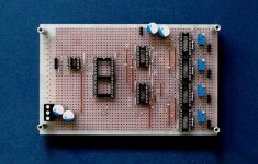
Ours was done on a Vero proto board with one common +/-5V supply for everything, and DAC internal opamp for IV conversion.
So this will only get better in the final build, especially in terms of 50Hz noise.
But maybe you can still reduce the odd harminics further by trimming.
Patrick
.
Just for comparison, the PCM56K measurement we posted a while ago, THD is about 2x.
https://www.diyaudio.com/community/...st-tht-i2s-input-nos-r-2r.354078/post-6925148
Ours was done on a Vero proto board with one common +/-5V supply for everything, and DAC internal opamp for IV conversion.
So this will only get better in the final build, especially in terms of 50Hz noise.
But maybe you can still reduce the odd harminics further by trimming.
Patrick
.
Attachments
Last edited:
That looks really good. Unless I’m missing some other non-DAC influences, it seems that .0025% is the AD1862’s limit. I figure I have .005-.010 or so to squash before I get the final picture 🙂 Either way, I’ve picked up a lot from the previous posts, so I think my confidence in the next batch of measures will be higher.
I haven’t installed the trimming conponents yet, but I do have them on hand. Most of the MSB measurement procedures I’ve seen involve a scope, which I don’t have at the moment. Is it possible/likely I could see some real-time impact via FFT if trimming on the fly?
I haven’t installed the trimming conponents yet, but I do have them on hand. Most of the MSB measurement procedures I’ve seen involve a scope, which I don’t have at the moment. Is it possible/likely I could see some real-time impact via FFT if trimming on the fly?
- Home
- Source & Line
- Digital Line Level
- DAC AD1862: Almost THT, I2S input, NOS, R-2R