But it has feedback while not the opa861 - please trust Pedja Rogic, I use everyday a dac of him and can say he is not false with that. and my tda1541a crown and can also compare with a late Korean best made build of this chip, and very complex clocked ffofed, isolated ground digital front end-
Proof is in the cake icing when seing your face on it and the importance of the front end in general and diy in particular 😉
Proof is in the cake icing when seing your face on it and the importance of the front end in general and diy in particular 😉
Last edited:
...
You can also use a 861 reversed instead the LME for the buffer. the 861 has no feed back s quiet simple.
I tried it, is working only for a higher impedance load (1k and above), is not possible to use it directly for headphones ...
Last edited:
LME49600 is buffer without feedback ... the internal diodes are only for a thermal stability, are not? or a protection?
otherwise the circuit in my post #317 is without feedback
otherwise the circuit in my post #317 is without feedback
Last edited:
where can I get a LME49600 🙂
yes noticed it wasn't feedbacked on your sim. Again any resistors between the opa 861 & the the LME ?
Yes, the way Rogic use it is in front of a pre/amp typically 25k to 100k input, not an headphone.It's also that I believe your design disearve also not just the headphones path : cool one can adapt in relation to his needs 🙂
Valuable information here fella’s. Thanks 🙂
I never use headphones, this Dac will feed a preamp 100% of its time.
I already have OPA860’s in my parts bin, but will add the 861’s and LME49600’s to the next order. Shouldn’t be to difficult to try both options.
I never use headphones, this Dac will feed a preamp 100% of its time.
I already have OPA860’s in my parts bin, but will add the 861’s and LME49600’s to the next order. Shouldn’t be to difficult to try both options.
Last edited:
... Shouldn’t be to difficult to try both options.
It would be best if you can try both. Tell us about your progress 😉
I don't know the Lme, but I will trust miro as the opa 861 is maybe not the ideal in reverse use as a buffer while honestly i can not hear the difference with or without it driving a 45k pre. 861 + 49600 + the R? outputt resistor and eventually a try with ears between both with & w/o resistor could be funny to know what are telling the ears from all of that. You also can use th eopa861 with a ? 700/1k serie resistor direct to the pre and if already protected at input without dc blocking cap and with a 750 ohms resistor as i/v if the pre is not far? - needs an offset triming w/o dc blocking caps between the two L&R channels ???
Well it's outside the pcb discussion. waiting the pcbs.
Well it's outside the pcb discussion. waiting the pcbs.
LME49600 is identical with BUF634, it can be slightly different in some parameters, otherwise the internal structure seems be the same (according to internal diagram in datasheet).
>10k is high impedance, buffer can help but I don't know if audibly.
You can use the series resistor, it will not harm.
I'm not sure about dc trimming, try it without. The output DC offset seems be small, about 9mV in this simulation.
>10k is high impedance, buffer can help but I don't know if audibly.
You can use the series resistor, it will not harm.
I'm not sure about dc trimming, try it without. The output DC offset seems be small, about 9mV in this simulation.
BUF634 has a fairly recent upgrade to BUF634A - https://www.ti.com/document-viewer/BUF634A/datasheet/features-sbos0301231#SBOS0301231
Hi Diyiggy,
While some of this chit chat is about what’s happening “outside the pcb”, it’s all tied together with what’s happening “on the pcb”. 🙂
Sharing information from everyone’s experiences really helps to get going.
So far, with the Dac board built as spec’ed, I’ve tried AD1611, LM6171, Burson V5 & V6, all have sounded very good. I will build a second board with some modifications to allow the use of OPA860/861 OTA’s. Hopefully, I can get two working boards to quickly A/B listen.
Yes, my preamps all have input capacitors and amplifiers are DC protected 😉.
... Hopefully, I can get two working boards to quickly A/B listen.
perfect Vunce, test it ... if it helps, I could create a small PCB for I/V socket, vertically oriented ... (with +-5V regulators on the pcb) ... or can you test on a breadboard pcb?
For anyone building Miros board, you shouldnt install the MSB adjustment components unless you plan to tune with an analyser straight away.
While it allows fine adjustment of MSB it will also allows the MSB to be severly misaligned causing massive crossover distortion, only a tiny fraction of the trimmer's range has precision the same or better than the chip without the MSB adjustment parts installed
While it allows fine adjustment of MSB it will also allows the MSB to be severly misaligned causing massive crossover distortion, only a tiny fraction of the trimmer's range has precision the same or better than the chip without the MSB adjustment parts installed
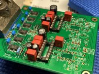
Second board is ready for Transconductance Amplifier I/V experimentation. I will implement Miro’s schematics from posts #317 & #320 via breadboard.
Just waiting on some parts now 🙄
Just waiting on some parts now 🙄
Attachments

- Home
- Source & Line
- Digital Line Level
- DAC AD1862: Almost THT, I2S input, NOS, R-2R