


Regarding the image of an I2SoverUSB a couple of posts up, why disable the galvanic isolation with jumpers? Not a good idea...
Thanks, Markw4, I am new to this, will try out the other option listed in the manual below soon. I am lucky that the board was up and running in no time, so I leave it that way, till now that you mentioned it.
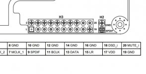
Power I2SoverUSB v.III board:
2. Bus-powered USB side and external power supply for oscillators and reclock.
In this case there is galvanic isolation between the USB side and user
application side. Plug the USB cable to USB B connector, provide external
power supply to H3.17 and H3.19 (4.5V to 5.3V). Consumption from USB host
is less than 400mA, consumption from external power supply for oscillators and
reclock is less than 100mA.
I got my DAC running. I built another board without the shift registers. But could not get it to run with the Raspberry PI.
I did try try reflowing the pins on the original board I built, but it still did not work. That could have been the Raspberry PI and not the board. I did not try a computer with it.
Now to get it into my and systems to hear how it sounds, and play with some OPAs and other outboard I/V circuits.
I did try try reflowing the pins on the original board I built, but it still did not work. That could have been the Raspberry PI and not the board. I did not try a computer with it.
Now to get it into my and systems to hear how it sounds, and play with some OPAs and other outboard I/V circuits.
Attachments
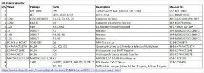
I2S Inputs Selector 3x/2x Input to 1x Output
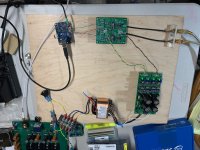
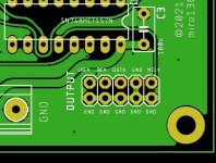
Here is digital input/output selector prototype made from THT components
It allows 3 or 2 I2S sources to be directed to one I2S output.
The input is switchable by a simple monostable tactile button. Each LED diode act as indicator for a selected input. Both, LED and button can be wired to a front panel. Each LED diode act as indicator for a selected input (diodes can be wired to a DAC panel).
I2S connectors include MCLK, BCK, LRCK, DATA, (GND) signals.
Parts are selected for TTL compatible inputs (3.3V-5V) and the output has 5V level, powered from +5V supply (parts can be selected for 3.3V power supply and 3.3V input/output level).
For example, it allows any I2S source (USB-I2S, SPDIF or Optical-I2S, RPi-I2S, Bluetooth-I2S, MCU-I2S, or similiar interface) to be switched to an I2S DAC. Theoretically it could switch any digital signal (up to 50MHz? 😕 )
There are many similiar ready-made input selectors for a few bucks, but why not DIY your own? 😛
It is untested 😱, please inform me for any error and I will do a correction 🙂
Mouser components example:
1x 653-B3F-1000
3x 630-HLMP-4740
5x 80-C322C104K1R9170-R
1x 667-EEU-FR1H101
2x 652-4309R-1LF-10K
1x 594-MBB02070C1001FCT
3x 594-MBB02070C1801FCT
2x 594-MBB02070C1002FC1
1x 512-BC548BTA
3x 595-SN74AHCT157N
1x 595-CD74HCT164E
1x 595-CD74HC4017E
1x 651-1729128
4x 571-1032405
Attachments
-
diyAudio_I2S-Inputs-Selector_2021-10-29.zip460 KB · Views: 141
-
 diyAudio_I2S-Inputs-Selector_BOM.jpg194 KB · Views: 462
 -
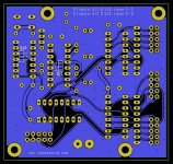 diyAudio_I2S-Inputs-Selector_Bottom.jpg257.6 KB · Views: 415
 -
 diyAudio_I2S-Inputs-Selector_Top.jpg335.2 KB · Views: 521
 -
 diyAudio_I2S-Inputs-Selector_Schematic.jpg494.6 KB · Views: 583
Great idea! Exactly this is in my planing 🙂
As I can see, many use the I2SoverUSB, so why not just make at least one input pin-compatible with the I2SoverUSB and the output pin-compatible with the DAC?
So you can stack the boards and hardwire them for the shortest possible connection 😀
As I can see, many use the I2SoverUSB, so why not just make at least one input pin-compatible with the I2SoverUSB and the output pin-compatible with the DAC?
So you can stack the boards and hardwire them for the shortest possible connection 😀
Miro
Just another couple of thoughts on this:
Many of us here us Andrea Mori's excellent clocks which allow for multiple clock outputs. If we have 2 sources, eg SD card player and USB card, but using one set of clocks. This means the enable line from the source device needs to turn on the clock output, and this needs to work from either device. Up until now, the only way I thought this could work was by powering off the device not in use. But is there a way that this could be done using your board. This would mean that switch would also have to be able to take the enable lines from both sources, and feed back out to eg 2 clock sources?
Second - many of us reclock the signal before the DAC. It would be useful to have a reclock chip on the output as an option after the switch - ie reclocking just before the DAC. There is a TI chip which is really useful for this because the inputs and outputs are on opposite legs. Much easier than eg the potato semi flip flop and others which have different in/outs.
Anyway, just thinking aloud, and it may be too complicated, or not needed by enough people.
@Kuka Do you mean a simple shield PCB 🙂 I could create something in a near future 😀
I meant same pin-layout for I2S in/out. So You can place the boards on top of each other and avoid I2S cables using short hardwired bridges.
Attachments
@woodturner-fran
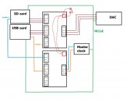
Do you mean something like this? Maybe 2 switch boards could do the job, but I am not sure if that is what you mean 🙂
One tactile button controlling both switch boards.
So the setup is that you have 2 sources, for example USB and SD card.
You have one set of Mori clocks - say 22 and 24 which can have dual outputs
Normal operation with one source is that an enable line goes high, turns on the Mori output for that frequency and mclk runs.
What can happen is that when both sources are on, and you switch the i2s as normal is that the USB or SD device keeps one enable line high - which means that both Mori clocks can be kept turned on. In practice the device that then plays ends up getting the Mori frequency that it actually wants, but also gets the other frequency that the other source is still calling.
Maybe the best thing to do is power off the device not in use - that is probably the easiest thing to do.
fran
> So the setup is that you have 2 sources, for example USB and SD card.
> You have one set of Mori clocks - say 22 and 24 which can have dual outputs
> What can happen is that when both sources are on ....
Do you really want this mess ?
Is convenience more important than technical robustness ?
The clock detection and then selection has to come from the source (SD, USB, Rpi, ...).
So you have two signals from 2 sources.
And yes, you can use a (logic) switch to decide which one.
And then you send this on to your XOs to switch one on.
And then this poor thing now has to supply 2x source + nx DAC reclocker.
And then you need a clock fan-out.
And then you complain about added jitter.
😉
Patrick
spaghettis are not wanted in digital front-ends
It will be awesome. something like the GPIO connector seen on the Rpi : for instance pin header on the JLSounds pcb and female header plug on the Miro board with the right alignement needed for a simple stack without wires 🙂
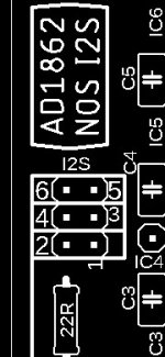
And in spite of making two boards, better to putt two input headers plugs : one going towards the register and one a little farer on the same side going direct to the ad1862s : in relation to the use of trhe I2S or the direct option AD1862 from the JLsounds board.
I personnaly like the uf-l Miro AD1862 board that permit the good uf-l wires, but they are only usefull for the ones having the I2S to PCM board from IanCanada : because the uf-l plugs on the AD1862 V1.3 from Miro are going straight to the dac chip and not through the registers : so you can not for instance use the I2S uf-l outputs of the Ian Rpi Fifo reclocker hat 🙁.
But some would then ask for a Miro ad1862 board with a gpio header arrengement compatible withe Rpi Gpio 😱 ... a never ending story 😀
...In the meantime I like the idea of an AD1862 board with two headers inputs compatible with the two ways the JLSounds is able to feed the Miro 's DAC (I2S trough registers or direct to the the dac chips in the AD1862 mode setuped by one resistor).
I don't think a shield stack a la IanCanada between sandwiched pcbs is usefull... more a gadget, cause the two boards have not to be upon each other like a story in a house and if you need global shielding for you to sleep better... then shield your enclosure with copper+ferrous screens 😱. ( my hand you will not hear any difference cause ems shielding is more to protect the devices arounds than isolate, and RF isolation is difficult and ask very experience gears to test it. Better a ferous shield upon your power transformers or a ferous vertical screen between the boards and the powersupplies that split in two envlosures your cabinet : the ferrous screen catch a part of the magnetic field that is also reduced by putting the traffos at 10 cm asomething feasible in an audio device cabinet.
I meant same pin-layout for I2S in/out. So You can place the boards on top of each other and avoid I2S cables using short hardwired bridges.
It will be awesome. something like the GPIO connector seen on the Rpi : for instance pin header on the JLSounds pcb and female header plug on the Miro board with the right alignement needed for a simple stack without wires 🙂
And in spite of making two boards, better to putt two input headers plugs : one going towards the register and one a little farer on the same side going direct to the ad1862s : in relation to the use of trhe I2S or the direct option AD1862 from the JLsounds board.
I personnaly like the uf-l Miro AD1862 board that permit the good uf-l wires, but they are only usefull for the ones having the I2S to PCM board from IanCanada : because the uf-l plugs on the AD1862 V1.3 from Miro are going straight to the dac chip and not through the registers : so you can not for instance use the I2S uf-l outputs of the Ian Rpi Fifo reclocker hat 🙁.
But some would then ask for a Miro ad1862 board with a gpio header arrengement compatible withe Rpi Gpio 😱 ... a never ending story 😀
...In the meantime I like the idea of an AD1862 board with two headers inputs compatible with the two ways the JLSounds is able to feed the Miro 's DAC (I2S trough registers or direct to the the dac chips in the AD1862 mode setuped by one resistor).
I don't think a shield stack a la IanCanada between sandwiched pcbs is usefull... more a gadget, cause the two boards have not to be upon each other like a story in a house and if you need global shielding for you to sleep better... then shield your enclosure with copper+ferrous screens 😱. ( my hand you will not hear any difference cause ems shielding is more to protect the devices arounds than isolate, and RF isolation is difficult and ask very experience gears to test it. Better a ferous shield upon your power transformers or a ferous vertical screen between the boards and the powersupplies that split in two envlosures your cabinet : the ferrous screen catch a part of the magnetic field that is also reduced by putting the traffos at 10 cm asomething feasible in an audio device cabinet.
Last edited:
Do you really want this mess ?
Is convenience more important than technical robustness ?
Patrick
I won't disagree!! But it is handy to have switching between 2 sources in one build. It gets very complicated very quickly though.
I2S switches can add some jitter. If that is a concern then reclocking with D-flip flops after the switch and just before the dac may help. However that approach requires a low-jitter master clock at least twice the frequency of the highest frequency I2S signal. Switching between master clocks is probably best done with small gold contact relays. There are some relatively low cost RF relays available if shielding and impedance control are desired.
- Home
- Source & Line
- Digital Line Level
- DAC AD1862: Almost THT, I2S input, NOS, R-2R