Thanks for all the messages.
Yes, the resistors R10 & R11 are there.
Mu opamp: LM6171BIN/NOPB
I am waiting for adapters to check other 2 opamps I have.
I Will ask the vendor of the board for some guidelines and report back next week when back at the workbench.
Have a good one.
Yes, the resistors R10 & R11 are there.
Mu opamp: LM6171BIN/NOPB
I am waiting for adapters to check other 2 opamps I have.
I Will ask the vendor of the board for some guidelines and report back next week when back at the workbench.
Have a good one.
wow nice project
currently I'm using AD1865 with commonly used input CS8414 and 74HC04, i also have AN dac red pcb that is used in level 4/5. my friend previously reverse pcb ccs layout and build the same supply and the result is amazing compared to regulated one using LT1085/1033
i bought cheap aliexpress usb to spdif (around $4) but looking around for i2s solution and read this thread. however i find that this thread board use same PCM2706 just like my board. is there any benefit using xmos board like this one?
XMOS 32Bit 384kHz DXD DSD256 USB to/from I2S, to DSD/reclock SPDIF PCB - DIYINHK
but my biggest question is, how can i get AD1865 board? i don't any GB link on first page
front end quality is a big part of the final result
Hi,
Yes there is : better SQ. But the DIYINK one is not so good VS some others like the JLSOUNDS talked there and also the Wave I/O pcbs.
Despite there are isolators on all those boards, power supply matters as the USB streamer before those boards. For instance a pc or laptop USB streamer will be more noisy than a dedicated streamer with low noise.
You of course can go for a Rpi with an Allo Kali reclocker or a IanCanada FifoPi stacked on it.
There is a Miro uf-l input board version but the uf-l pads go straight to the dac chips without passing trough the shift registers, so only for those having an I2S to PCM board; The JLSOUNDS can output both towards the registers or direct to the AD1862 dac chips, but having not the uf-l pads better to go to the Miro's board 1.2 (lower oap form factor but if you need DIL8) if you don't need uf-l pads/wires.
I have a AD1865 AN clone as well (spidf, same spidf chip as yours) : the AD1862 is in a way better another league. Go to the first page of this thread for the links 😎 in relation to what oap size you want to choose.
Last edited:
previously i had Himedia Q10 pro, a junk streamer which can only use my 1TB usb disk, no response with 4TB. can only play full hd, no capable of 4k even if it has the sticker on it. then continously hang and should be hard reset. at the end it end up in my garbage
i finally bought a cheap ex-office dell pc with i7 + 8GB + ssd around $200, yes intel vga can only support full hd so i had to buy nvidia 1030 low profile. but now i can even play COD4 or 6 and BF4 smoothly, play 4k remux without any issue
i'm sick of any streamer type now, expensive with 2 or 4 GB ram only, silly processor. regarding "noise" pc, i still don't get what exactly people are complaining about. i turn up all of my preamp volume and don't hear any noise at all with my ear on the speaker. no possible way i can hear music at this volume, my ear will bleed, my potentiometer usually around 12 o'clock
I'll read again some early page of this thread, AD1862 or 1865
read it as "noise floor level" if you prefer as rendition is different with a good hifi with different streamers qualities. Anyway, shorter ground loop also often go with better sounding result ! 🙂
Allo has also a Rpi pcb not that expensive which is less noisy than the Rpi. And not noisy smps on the computer boards as well as PC/laptop main smps unit. Each improvements matter, like clock board and so on. Of course up to you, but the AD1862 dac chip worths it and the good pcb is allowing too to choose good power supplies.
Advices were just in case you haven't streamer yet 😀
Last edited:
maybe someday streamer is an option, or hardcore pc build with linear supply and huge toroid just like lampizator.
I still have unfinished TentLabs cdpro2 kit, making i2s output is an option instead of spdif
btw, where is the link to buy this project pcb? i can't find it
I still have unfinished TentLabs cdpro2 kit, making i2s output is an option instead of spdif
btw, where is the link to buy this project pcb? i can't find it
Attachments
pcb is free, curtesy of Miro1360 for the comunity. links and BOM are in first post, it's cheap at JPLCB and they ship fast.
@Decek
Connect it on a different power supply (lab power supply). If you don't have a lab power supply, create the simplest voltage regulator from 78xx/79xx components, measure output voltages and test it 🙂
VRDN is based on the LM317 regulator. This regulator can't handle high capacitance low-esr at the output. In that case you can add some resistance to the voltage wires.
Is the "white" +-5V regulator connected correctly? Input/Output.
@gadut
As diyiggy said, all my PCBs are free for download and use. Download it from post #1351 (gerber file in zip), open your prefered PCB manufacturer (like jlcpcb) - login or register on the website, upload the gerber file on the website (click quote or click on "Add gerber file"), leave default settings or change something (color, quantity), click on Save to cart, then Checkout and select reasonable shipping for your country.
It is the cheapest way how you can get as many PCBs as you want, but opt for cheap shipping with tracking number.
i thought there is a separate GB for the pcb, i never order any pcb on my own yet. I'll try on that provider
Gadut I encourage you to order boards as it opens up a new world of DIY. Cheap too.
I have a spare board if desperate.
I have a spare board if desperate.
Gadut,
Better for the Sumatra forest that the pcbs are sent from China to Indonesia in spite of China-GB -> GB Indonesia ! And cheaper too about stamps !
Be confident to that provider and choose 15 days shipping you will be surprised by the low cost and fastness. Better to not choose golden traces/vias for the pcb by the way !
As you have to buy 5 pcbs minimal order yo will have as well new friends for the ad1862 pandemia. Please send one to my Batam fella Sumotan member please which is a TDA1541 tweaking compagnon 🙂, as you are very close from each others 😎 !
As Jim said, it's easy, it was the first time too I uploaded gerbers to a fonder despite I already soldered many dac projects... brand new experience, cool 🙂 !
And as you are here, the 5V/12V power supply pcbs are good too 😉 !
@diyiggy
i rarely jump into dac subforum lately, but yeah i noticed sumotan because he has same user id in my local forum just like mine. i think he is just too crazy for his journey, playing with exotics parts 🙂
i consider my journey as completed previously, enjoyed playing my ripped flac to blank cd on my dvd player as main source. but now i have left it behind and i find Deezer Hifi is my ultimate flac collection. no need to think of maintaining my files anymore and i can listen to millions of song compared to my cd collection.
btw i tried to make quotation. is this real??? only $2 and $1.7 for shipment? that's crazy if it's true
i have bought many pcb for my build overseas, indeed it's not cheap
Attachments
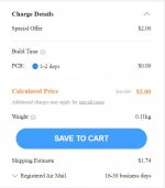
that's indeed that price.
No, he is not crazy, just experienced and have some requirements as I.
No, he is not crazy, just experienced and have some requirements as I.
I'm trying to figure out the setup for the I2SoverUSB v.III. I'm not sure if I'm supposed to use:
1. PCM1704 like protocols on board oscillators
J2 - Open, J3 - Open, J4 - Close, B1 - Open, B2 - Open, B3 - Open, B5 - Open
or
2. PCM1704 like protocols with external MCLK
J2 - Open, J3 - Open, J4 - Close, B1 - Open, B2 - Open, B3 - Open, B5 - Close
Which one is for the shift registers installed and which is without?
Also, is there a difference between using the shift registers or bypassing them, since the I2SoverUSB v.III can be configured so that it does not need them?
I had the boards I had fabricated are V1.3 with uf.l. Would I connect Data R to JP1 and Data L to JP2 on the board?
Can't wait to get this DAC operational.
There is sound only in the right channel, left channel has oscillation, both DACs. On the sound side when I turn on the DACs with only the right channel working the sound is vibrant and "alive". One OPA627 in the right side DAC with white marking is really vibrant, this was the batch of 10 OPA627 which I bought from T.I official distributor, while ones with black markings I purchased from ebay by judging the output I think they are remarked.
Just read this. OPA627 devices I obtained from eBay had internal offset voltage resistances on pin1 and pin5 connected to the negative rail instead of the positive rail, hence fake parts. All you need is an ohmmeter to verify a resistance value from pin1 to pin7(positive) and pin5 to pin7 if the part is legitimate. If you know what the resistances ought to be all the better. Mine had resistances to pin4(negative).
Hi all,
Anyone knows where I can get authentic 74ahct164d or 74hct164d? They are obsolete and out of stock at digikey and mousers. Are there any direct replacement chips available?
Many thanks.
Anyone knows where I can get authentic 74ahct164d or 74hct164d? They are obsolete and out of stock at digikey and mousers. Are there any direct replacement chips available?
Many thanks.
- Home
- Source & Line
- Digital Line Level
- DAC AD1862: Almost THT, I2S input, NOS, R-2R