The CCS Denoisator with two BJTs in parallel (BC5x0) almost reaches the reference amplifier noise from this comparison: https://linearaudio.nl/sites/linearaudio.net/files/v4 jdw.pdfThis noise reduction game is completely useless.
Even the connection cables between the output of this module and its load will capture tens-hundred times more noise. And it uses an infinity of pieces. The simple version with 1 transistor is more than enough. Maybe only the slightly more advanced versions with 2-3 transistors.
I think with two ZTX in parallel it bests that as well. I think it's good enough as far as noise goes. And with a LM317-N it should have around 120dB of PSRR. Last measurements were done with a regular ST LM317.
Maybe for some particularly demanding circuits you could build a NoNoiser which is a different level of "low noise".
In all these last variants that I have presented, calling them "multistage" for the moment, they would offer a clear improvement in the high frequency area, compared to all previous versions. We would have to wait for rigorous laboratory tests.
Best regards
Last edited:
Elvee, can you elaborate this opamp "servo" based LM317/337 circuit please? Does it rely on same principle as d-noizator? Can you compare their pros and cons in terms of impedance, noise, PSRR etc. please?

This circuit has already appeared earlier in the thread; it is based on the same principle as the x-noisers, except the active element is an opamp.
The advantages of opamps are the flexibility in the choice of auxiliary components, the fact that the output goes directly to R4/R5, meaning there is no need for large C16/C20 to avoid frequency peaking.
The cons are the higher cost, the necessity to make the supply bipolar, and most important, the performances: even with low R10/R11, it cannot come close to the noise of a BJT, even a humble BC338 or similar

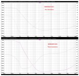
I was just curious about it and simmed in LTS. Psrr is very very poor, the original denoizator it's much better... and cheaper.
One question remains: is it stable? Only a physical test can answer for sure, but a transient sim with a very small timestep could already give some clues
It is a bad omen. You can try the usual tweaks, like changing the solver, Gmin, etc, but I think they won't work, because the circuit itself is the cause and tries to oscillate madly as soon as the power is present.
There is much too much gain, and no compensation at all
There is much too much gain, and no compensation at all
If I run .tran, what is the correct result to show?
I just ran it on the original Denoisator and the original Dienoiser. On the first I got a curve, on the second I got a straight line.
Which is the correct result?
I just ran it on the original Denoisator and the original Dienoiser. On the first I got a curve, on the second I got a straight line.
Which is the correct result?
If you run a .tran sim without any options, you should get a more or less straight line, maybe with a stabilization period of a few seconds. The thread has many examples of transient simulations, often with different startup conditions to see what happens in a cold-start situation.
In doubt, post a screenshot of your result
In doubt, post a screenshot of your result
Then, the voltage should be ~stable from the startNo, I used the same commands above for all sims. .tran 0 1 0 1u
For PSRR, yes. However, the output noise and impedance benefit from the denoiser in all cases.these tests really impress in the 100hz/120hz range which seems to be the main target.
At high frequencies, a simple LC filter can be very effective and use moderate value components
Is there a .tran sim for the Denoizator and Nonoiser anywhere in the thread?Then, the voltage should be ~stable from the start
I have tested the two-transistor version.
To make it stable (in sim only, of course), I had to increase the compensation cap to 47nF, and use a very low esr 100µ output cap, but the stability looks very marginal, and the regulator model is more tolerant than its physical counterpart:

To make it stable (in sim only, of course), I had to increase the compensation cap to 47nF, and use a very low esr 100µ output cap, but the stability looks very marginal, and the regulator model is more tolerant than its physical counterpart:
Attachments
Can any of these circuits be adapted for 280Vdc use? just change the BITs and caps for the higher voltages?
- Home
- Amplifiers
- Power Supplies
- D-Noizator: a magic active noise canceller to retrofit & upgrade any 317-based VReg