With 5 transistors alone you can get one of the finest regulators you could possibly use in audio
Elvee felt the required number was closer to 11 transistors. Just for fun: a superreg with <12 discretes??! ?! ?

I think he meant 11 total discrete parts, not transistors.Elvee felt the required number was closer to 11 transistors. Just for fun: a superreg with <12 discretes??! ?! ?
If bad tempco is not an issue then this is a pretty good option for only 6 extra parts compared to a regular Cadj application for LM317.
Measured PSRR was over 140dB at 100Hz and noise floor level well under 1nV/sqrtHz.
have a look at post number one, elvee has included a detailled index with linked references!it's damn hard to follow this interleaved discussion
I saw it, but it doesn't solve the problem for 2500 posts, nor it will for the next 2500.I wonder why hacking threads is called infraction...

You can just use a LM338 instead of LM317 if you need up to 4-5A. The performance is practically the same to LM317.
I thought maybe this method would be great for FM Transmitters.
Pulling a continuous 5 Amp through the LM338 seems worrisome.. 😵
Pulling a continuous 5 Amp through the LM338 seems worrisome.. 😵
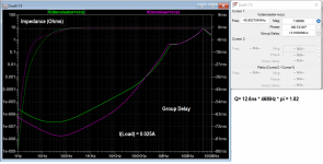
It does seem to work but not sure if it's a sim fluke or really works. Would have to be tested.

Should have even better performance with the CCS+Nonoiser.
Sim is for 4Aout.
edit: I forgot to add Q2's base resistor. With it it doesn't work.
Should have even better performance with the CCS+Nonoiser.
Sim is for 4Aout.
edit: I forgot to add Q2's base resistor. With it it doesn't work.
that fast...It does seem to work but not sure if it's a sim fluke or really works. Would have to be tested.
View attachment 1120091
Should have even better performance with the CCS+Nonoiser.
Sim is for 4Aout.
edit: I forgot to add Q2's base resistor. With it it doesn't work.
is the graph for output impedance?
what is actually the function of R8? does it not limit the output current (by Q4 VBE)?
its value seems too high.
It's the PSRR graph.
Actually seems to also work with Q2 base resistor, I tried with 1k but I have to increase the compensation values, and also add around 5R in series with the existing C1.
Not sure if you can get by without Q2 base resistor. With a regular LM317 implementation Q2's base current shoots up to 35mA at startup, but with the denoiser circuit barely goes to 0.5mA, at startup. Same with Cadj. So you might be able to skip it in which case the denoiser circuit seems to work fine, even at 4Aout.
NoNoiser seems to work as well with great performance at 4Aout, but you need the denoiser's base resistor (R11/R12). It does raise the noisefloor a bit but it's still extremely low. Clearly this would have to be tested.
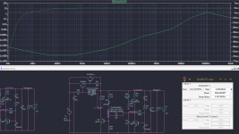
I attached the LTSpice sim file, set for 4Aout, with both CCS+Denoisator and CCS+NoNoiser.
Upside of this vs LM338 is it should work for LM337 as well.
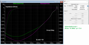
edit: changing Rload to 1.5R for 8Aout doesn't seem to change anything. As long as your pass transistor can take it.
also the denoiser circuit is hot rodded at ~12-13mA.
in the sim case the LM317 takes around 100mW so you could use a TO-92 (costs ~0.50€) or SOT-223 package on the PCB, which would take up less space. no need for a heatsink, for the LM317 package. these SMD or smaller THT packages are 100mA rated which is enough. Sim shows under 40mA needed for LM317.

I attached the LTSpice sim file, set for 4Aout, with both CCS+Denoisator and CCS+NoNoiser.
Upside of this vs LM338 is it should work for LM337 as well.
edit: changing Rload to 1.5R for 8Aout doesn't seem to change anything. As long as your pass transistor can take it.
also the denoiser circuit is hot rodded at ~12-13mA.
in the sim case the LM317 takes around 100mW so you could use a TO-92 (costs ~0.50€) or SOT-223 package on the PCB, which would take up less space. no need for a heatsink, for the LM317 package. these SMD or smaller THT packages are 100mA rated which is enough. Sim shows under 40mA needed for LM317.
Attachments
Last edited:
Sorry, I missed your post.@Elvee can we add D'Noiser to the "default" High Current circuit in the datasheet?
does it need some tuning? like changing the D'Noiser Collector current.
View attachment 1119529
Trileru has replied, but the general rule is to avoid mixing the denoiser with other hacks.
The sim might look OK, but I have no certitude about the real behaviour. Before committing to it, you should try on a quick and dirty prototype, to avoid any unpleasant surprises.
The current boosting hack alone seems to work reasonably well for the 317, but it is unstable with the negative 337
Yes I'm having some issues but seems to work to some degree in LTSpice (with current boosting). More testing needed.
At 8Aout:

At 8Aout:
Last edited:
When I want to get closer to reality I use TI's LM317N model, I found it to simulate closer to my measurements.
I did experiment with parasitic inductance, 5-15nH I figured is the variation between less and more inductive electrolytic capacitors.
I did experiment with parasitic inductance, 5-15nH I figured is the variation between less and more inductive electrolytic capacitors.
Attachments
what is actually the function of R8? does it not limit the output current (by Q4 VBE)?
its value seems too high.
I think that sets a minimum current for Q2.
From here https://sound-au.com/articles/cmpd-vs-darl.htm (1 - Basic Configurations)The base-emitter resistor (R1, shown in each of the configurations in Figure 1) should be sized to ensure that the drive transistor has a collector current that's above the minimum. The resistor also helps to ensure a faster turn-off and minimises leakage current.
If using Q14 which by the way is lower power than lm317, what's that lm317 regulator supposed to do?
I just checked National and Texas instrument lm317 datasheets and it occured to me that the whole nonoiser concept is wrong because it cannot deliver 50uA bias current to ADJ pin at all time, especially at startup or in overload mode.The lm317 designer specified a current path for ADJ pin to output not to ground and a minimum input to output voltage.Getting that current through q17 alone is a design mistake.Just read the datasheet and make a simple current calculus for minimum output voltage and you'll see it's simply wrong to have a 2k7 resistor from adj to output.You didn't improve the boost circuit from TI datasheet at all, on the contrary.All you need is a fast dead short at the output to make an oscillator.No noiser makes no sense because it's not using lm317...You can remove it and replace it with a zenner honestly...
Last edited:
The LM317 is agnostic regarding the current generated by the Adj pin: in the datasheet, the resistive divider has lowish recommended values, to eliminate the effect of the current on the output voltage, but that's it basically.
If you remove the 2K7 completely and use a reference voltage, a battery or similar to GND, it will work perfectly.
In fact, the 2K7 could be removed completely, but the variations of the Adj current would slightly influence the Vbe of the transistor; the current through the 2K7 swamps the variations completely, because the dynamic resistance of the BE junction is much lower than the recommended 240ohm of the DS with the set current
- Home
- Amplifiers
- Power Supplies
- D-Noizator: a magic active noise canceller to retrofit & upgrade any 317-based VReg