I think the idea is to not use capacitors in parallel that are more than x100 difference in value.
Hi guys,
very nice and long tread! I did not have time to read it all.
Clever circuit!
I think I have seen something similar in the past but can't remember exactly where.
Anyway, I just put together the 1 transistor circuit and got good results - 30dB lower noise (5Hz - 20kHz) but the transition response is not impressive, which means a constant very slow oscillation in the real world, approximately 0.5uV per 1mA output current.
Has anyone encountered a similar behavior or it's just my layout.
Do you mean a real VLF oscillation, or simply noise?
VLF oscillation can occur if the ratio of the coupling capacitors (220µ & 22µ) is significantly smaller than ~10.
The HF limit of the correction is determined by the compensation cap: the larger, the lower
VLF oscillation can occur if the ratio of the coupling capacitors (220µ & 22µ) is significantly smaller than ~10.
The HF limit of the correction is determined by the compensation cap: the larger, the lower
Thanks for the prompt and helpful reply!!!
In attempt to improve he transient response and overshooting I reduced the capacitance of the input capacitor. Maybe that was the reason for the very low frequency oscillation (1-2Hz).
I did't read the whole tread and I used the circuit in the opening post. Is that the final design?
Thanks again
In attempt to improve he transient response and overshooting I reduced the capacitance of the input capacitor. Maybe that was the reason for the very low frequency oscillation (1-2Hz).
I did't read the whole tread and I used the circuit in the opening post. Is that the final design?
Thanks again
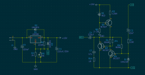
The first diagram is OK, but the final, recommended version is this one:
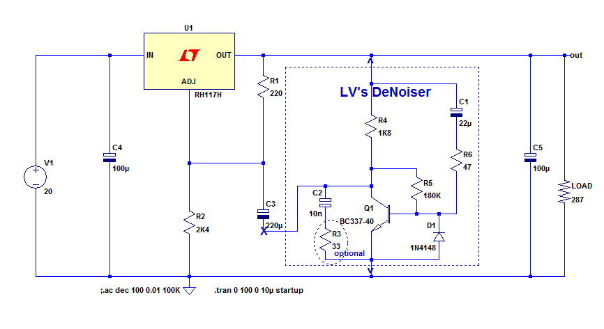
For a regular 317, R3 should be zero.
In principle, reducing C1 should increase the stability and reduce the overshoot, but I didn't test extreme values.
I recommend you start with the nominal values, and once everything works as expected, you can begin to tweak, to improve your preferred aspects.
For a regular 317, R3 should be zero.
In principle, reducing C1 should increase the stability and reduce the overshoot, but I didn't test extreme values.
I recommend you start with the nominal values, and once everything works as expected, you can begin to tweak, to improve your preferred aspects.
The first diagram is OK, but the final, recommended version is this one:
For a regular 317, R3 should be zero.
In principle, reducing C1 should increase the stability and reduce the overshoot, but I didn't test extreme values.
I recommend you start with the nominal values, and once everything works as expected, you can begin to tweak, to improve your preferred aspects.
Zero for R3 - How about for the 337 ? or a 5 amp 338 ?
Will reducing C1 to 10uf alter performance in any negative way ?
For the 337 and 338, I don't remember exactly, the answer is probably somewhere in the thread.
Reducing C1 will affect the VLF correction limit, but 10µF will not change the PSRR at 100Hz.
Reducing C1 will affect the VLF correction limit, but 10µF will not change the PSRR at 100Hz.
Last edited:
VLF oscillation can occur if the ratio of the coupling capacitors (220µ & 22µ) is significantly smaller than ~10.
I think for the discrete regulator versions this ratio is smaller than 1, around 0.5. Is that an issue?
It all depends on the impedance levels, and the frequencies of the poles they create in combination with the capacitors.
The topology also plays a role: you have used an inverting and a bootstrap one in your reg, and they have very different properties.
The bootstrap is certainly more difficult to analyze theoretically.
The simplest way to evaluate possible issues is to test several configurations in LTspice, with the stimulus somewhere inside the loop.
If you see a strong peak appear in the FR, you know that you have to dig a little deeper.
For the denoiser, I have adopted a tradeoff: I wanted a cutoff frequency below the audio range, but I didn't want the second capacitor to be larger than 220µF, as it would be too bulky. This resulted in a VLF bump and a bit of overshoot, but it remains acceptable

I made another board using LM317T + dienoiser, with bigger thermal dissipation.
These recently dog days are super hot here...KA7812 is still running for serveral hours w/o issue, but when I touch to the case (outside), feeling a little hot inside.
I found calculator for R1,R2 for the output 12.6v.
(220R/2000R). The actual output is 12.85v.
LM317 Resistor and Voltage Calculator


These recently dog days are super hot here...KA7812 is still running for serveral hours w/o issue, but when I touch to the case (outside), feeling a little hot inside.
I found calculator for R1,R2 for the output 12.6v.
(220R/2000R). The actual output is 12.85v.
LM317 Resistor and Voltage Calculator
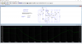
This is the behaviour of an example, unmodified:
There is a strong (almost 16dB) peak in the VLF range.
With the value of the first cap reduced, the peak is almost gone:
I'll try lowering the cap next time I'll tinker with it. Thanks for the info
A variation of D-noizator
Hi guys,
As I said in my first post I like very much the idea behind the d-noizator and the implementation as well.
For the purpose of the design - retrofitting power supplies based on LM317, it is maybe the best solution (when carefully implemented).
I put together the circuit and found out some minor details that would not fit my goals - very low frequency partial instability, transient response, overshooting, little bit insufficient PSRR. At the end of the day all these results in a fluctuation of Vin-Vout voltage.
SO lets limit that fluctuation. I gave a try to a very old trick - Tracking Preregulator. In that particular circuit the first regulator limits Vin-Vout voltage of the second regulator in very tight boundaries. As a result of that all mentioned before small issues could be partially or fully overcome.
After some quick measurements I liked the result very much - noise bellow 0.5uV (5Hz-20kHz, Iout 0-200mA), PSSR went down with another 25dB, no low frequency instability, better transient response.
Hopefully somebody will put together that simple circuit (it took me 30 minutes) and confirm my findings.
Attachments
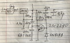
I just noticed that I've omitted to capacitors - between input and output of 7805 to GND. Both are 4.7uF
Good it solved your problems, but here the prereg can only improve one thing: the PSRR.
It is not going to improve noise, output impedance or transient response, as only the denoiser affects them, and it is certainly not capable of eliminating instabilites (if they are actually present)
It is not going to improve noise, output impedance or transient response, as only the denoiser affects them, and it is certainly not capable of eliminating instabilites (if they are actually present)
I have made some systematic tests on a number of 337's, since it is more temperamental than the 317 and can be difficult to tame.
The optimal compensation values vary somewhat with the source of the 337, but a safe, one-size-fits-all combination is 47nF-4.7ohm.
Recently fabricated samples do not require values that aggressive, but if you want to ensure a good stability without making detailed tests of the transient behaviour, they are a safe option and the impact on the HF performance of the denoiser is minimal.
These are valid for an ordinary transistor: the recommended type is BC327, but any other general-purpose type will also work: BC558, 2N3904, 2N2907, etc. (non-exhaustive).
A high perf transistor like the ZTX950 can also be used, but in the denoiser the performance gain over a BC327 will be small. For the dienoiser and nonoiser, it will significantly lower the noise floor.
The gain selection of the transistor is mostly indifferent: -16, -25, -40 or unselected types will work equally well.
The denoiser's performance is dictated by the transconductance, which does not depend on the gain, except that a higher gain type will bias itself at a slightly larger current, but this effect is compensated by the higher Hoe of higher beta transistors: the Early voltage is inversely correlated to the betaa, for a given process.
Stay away from "exotic" types, like VHF/UHF transistors: apart from problems, they will bring nothing to the denoiser
I found out exactly the same lack of correlation between the type of the transistor used and noise performance of denoiser. I noticed that the use of transistors with a gain > 600 may degrade the transition response though.
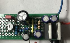
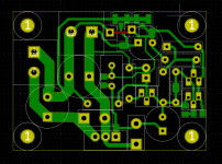
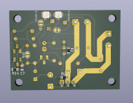
I built a LM338 board that also has the ccs option. I only tested it at 100mA out but I plan on testing it at around 4.5A.
At 100mA the PSRR at 100Hz is at around -138dB. Noise level seems to be around 645pV/√Hz (without LNA's noise). I used ZTX851/BC327 for the dienoiser and BC327 for the CCS. Needs a regular 5mm red led. The dienoiser current was set at around 9mA, with around 3-4mA through the LED. Increasing the dienoiser current makes for worse results, the LM338 doesn't seem to like more. 120R seems like a good value.
Compensation was 47n/1R. Output cap I used Elna RJH 120uF/35V, just because I had it and measured around 0.2R for impedance.
The board is to be used with DC input only. This way, especially for higher output current, you can have a separate rectification/filtering board. Board size is about 48mm x 35mm. Can be diyed.
I'll post measurements after I get to test it at 4.5Aout.
edit: voltage setting resistors are 0805 footprint, compensation network as well.
Attachments

Last edited:
- Home
- Amplifiers
- Power Supplies
- D-Noizator: a magic active noise canceller to retrofit & upgrade any 317-based VReg