I didn't see the schematic with the arrows, but anyway R9 has practically no influence on the 4-wire operation, and can be connected anywhere convenient
Not sure re the schematic. It was your post - I presumed you were referring to arrows present on most all of the Denoiser schematics (small arrows at top and bottom of the Denoiser circuitry).
So how about D2 in the schematic in post #2251 (the 1N4148)? The same diode in the Nonoiser is connected to the negative force line.
I have many variations on lm3x7 based power supplies for pre-amplifiers.
Finally made a DeNoiser. I did not expect a real sonic improvement.
I was quite wrong... single biggest improvement on all fronts.
Sincere thanks Elvee.
Finally made a DeNoiser. I did not expect a real sonic improvement.
I was quite wrong... single biggest improvement on all fronts.
Sincere thanks Elvee.
To Elvee or anyone who has built and tested the Denoiser or Dienoiser - what is the typical overshoot of the voltage ?
For a 12V output, it is 0.6V, thus ~5%. If it is an issue, it can be elminated by reducing the 22µF coupling cap to 15µF or even 10µF.
It will leave the 100Hz rejection untouched, but the VLF noise reduction will be diminished.
Better is to increase the other cap from 220µ to 330 or 470µ, but it is more expensive in cost and PCB area.
The dienoiser and nonoiser do not have such issues, but are more demanding regarding layout, etc
It will leave the 100Hz rejection untouched, but the VLF noise reduction will be diminished.
Better is to increase the other cap from 220µ to 330 or 470µ, but it is more expensive in cost and PCB area.
The dienoiser and nonoiser do not have such issues, but are more demanding regarding layout, etc
You should make dienoiser and get another improvement surprise. 🙂
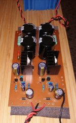
I made a fresh dual 317 15v supply board with dienoiser. bc3X7 40, and 22nf ceramic comp cap with no extra R. It is stable (not so with 337 on previous test riser boards, various comp configs).
The Denoiser is a huge benefit and more flexible.
Dienoiser is sonically slightly 'cleaner' sounding, different, needs to be on same pcb as regs.
I would be happy with either on a wet sunday.
I had voltage overshoot +3->6% with both circuits on riser boards and practically none with nice layouts on same pcb with similar components. Will try 10uf on riser boards, thanks!
Last edited:
It is stable (not so with 337 on previous test riser boards, various comp configs).
What output cap did you use for LM337?
@Elvee
It's been a while since i ran simulation for nonoiser but if i'm not mistaken amount of time to get stable voltage on output after powering on was quite longer then with denoiser.
P.S.
I'm not sure if you saw but i started to work again on PCB for your HP 428 probe and was thinking to put denoiser as PSU for it. Is that a good idea? Somewhere in corner of my mind there is info that you/or somebody else said that these type of PSU don't like a lot of uF on their output and there is gonna be quite a lot of decoupling caps there.
What output cap did you use for LM337?
Tried Panasonic fc, fr, Nichicon pw, TK jovial for output caps. Fc caps were 47, 100, 220uf. The others were 100uf.
Tried x7r, then poly comp capacitor. All resistors 1% metal film.
The dual LM317 board above has some Nichicon kz 47uf.
Amusing schematic found here. Click on the image to see it full size and undistorted.
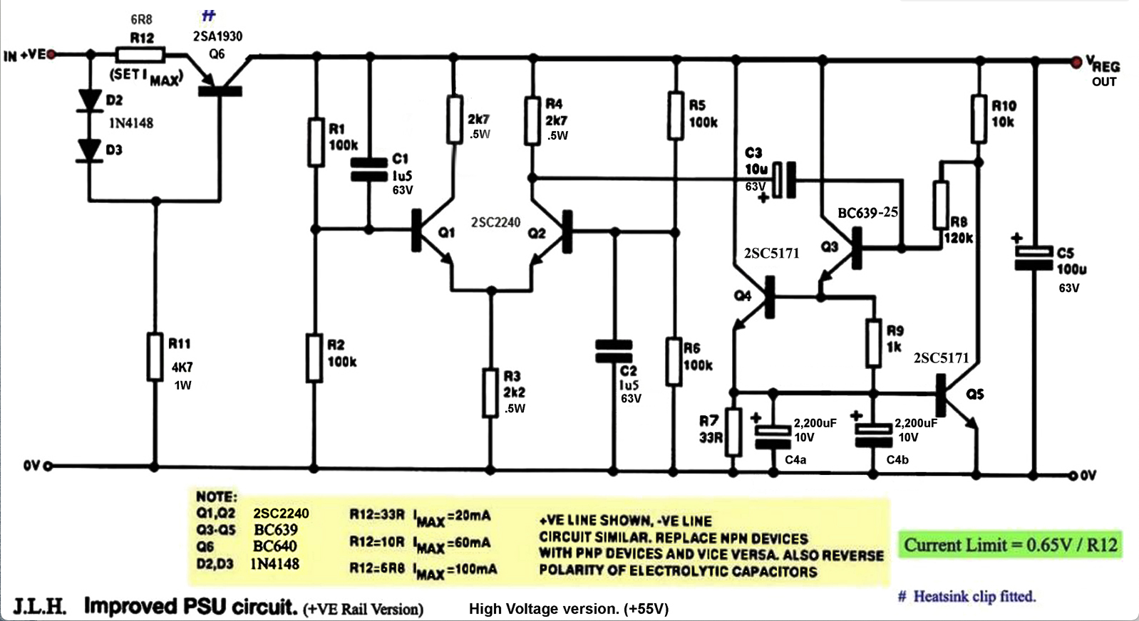
Many JLH Ripple Eater users report audible improvements when using this circuit in their power supply chain.
How does it work?
The circuit consists of two parts: a ‘ripple detector’ arrangement based on a long-tailed pair, and a constant current source. Any ripple voltage present across the supply line can modulate this current. The aim being that if the output voltage were to momentarily increase or decrease, the current drawn would automatically increase or decrease to oppose these output voltage fluctuations. The impedance of the circuit depends on the size of the capacitors used – particularly that of C4, which can be large since it only needs to be 1V working. With the values chosen in this iteration, the circuit generates the electronic equivalent of about half a Farad or more.
It’s also been observed “In essence it is an AC feedback loop”.
The original article contained a full circuit and application description, some of which I have paraphrased here. JLH also provided explanatory diagrams, a schematic
Last edited:
Tried Panasonic fc, fr, Nichicon pw, TK jovial for output caps. Fc caps were 47, 100, 220uf. The others were 100uf.
Tried x7r, then poly comp capacitor. All resistors 1% metal film.
The dual LM317 board above has some Nichicon kz 47uf.
The LM337 dienoiser was stable for me using a Panasonic FR 470uF/25V. It's not about the capacitance value, rather ESR and ESL. Around 40-50mOhm. There's two types of FR caps in that value (470uF/25V), I used the taller/thinner one. Also try some 3.3R/47nF for comp.
Amusing schematic found here. Click on the image to see it full size and undistorted.
I don't get it, there's no feedback to the pass transistor. And the rest of the circuit is just a load.
@Elvee
It's been a while since i ran simulation for nonoiser but if i'm not mistaken amount of time to get stable voltage on output after powering on was quite longer then with denoiser.
IIRC, the nonoiser does not have difficult tradeoffs regarding the proximity of the input and output poles, and can easily have a completely overdamped response without overshoot whilst keeping capacitor values reasonable.
If the caps are largish to maximize the correction efficiency at VLF, this will lead to a long ~exponential rise time, and that might be the option I chose for the published example, but I need to recheck it.
Yes, I noticed it. Congratulations, and the best of luck with your project. I do not think a denoiser would bring great improvements there, since the circuit was designed to work without it, but don't be afraid to use one if you want: the output of a denoised regulator has an extremely low impedance, and having a large sum of distributed, relatively distant caps is not going to affect it.P.S.
I'm not sure if you saw but i started to work again on PCB for your HP 428 probe and was thinking to put denoiser as PSU for it. Is that a good idea? Somewhere in corner of my mind there is info that you/or somebody else said that these type of PSU don't like a lot of uF on their output and there is gonna be quite a lot of decoupling caps there.
Using a large, low esr/esl cap directly connected to the output would be problematic.
Be sure however to include the mods I recommended to Sam: my build happened to work perfectly without them, but they are necessary if you don't want to rely on luck and after-build tweaks.
The circuit is similar to the "Finesse" circuit example I gave at the start of the thread. It is in fact a shunt regulator, but without a fixed voltage reference value.I don't get it, there's no feedback to the pass transistor. And the rest of the circuit is just a load.
It is the shunt version of the more usual series cap-mult/gyrator ripple-eater.
Not very efficient or convenient.
It is in fact a shunt regulator, but without a fixed voltage reference value.
It is the shunt version of the more usual series cap-mult/gyrator ripple-eater.
Not very efficient or convenient.
Ah yes, completely missed R12 at first glance.
I updated schematic to get output 24VDC and heatsink is SK129 6.5C/W so that LM317 will be cold.
I would like to push Dienoiser to it's maximum so:
- added RCRC filter and from simulation i got -172dB PSRR (so we pushed PSRR at their maximum).
- ZTX851/951 was choosen for Q1 and Q2 to get the lowest noise possible (below 1nV/Hz)
- added two LM317 and use of dual secondary toroid to get output of +/-24VDC (because LM337 is not good as LM317), LM317 is connected in series - like battery to archieve +/- output voltage at same parameters.
QUESTION:
- can we have remote sense with kelvin sensing? This way Kelvin sensing will be sensing output connector on PCB where we connect wires for V+ GND and V-, and remote connectors in + and - side with 10R resistor will be sensing on preamp and compensate long wires and make the voltage at remote preamp stable. If we can add remote sense could you draw in paint where need to go where wires for remote sense connectors?
- on LM317 i see that many schemes have 1N4007 diode between IN and OUT of LM317 for extra protection...should i added it to schematic and does it will ruin performance? (Zout?)
- 5k potentiometer is connected to VGND, is it better to add bettween potentiometer and VGND a resistor, say for example 47R?
- do we need to add current limiter before IN of LM317? I ask this if we power up first time preamp and there is something in short, preamp will pull more that 1A and LM317 does not have current limiter, so it will get very hot and shutdown....so adding current limiter make sense or not?
Thanks.
Here is schematic that i im preparing for PCB Layout when i got all questions answered.
What values for C18 and C21?
A little off subject, but will this circuit work for lm7815/lm7915?
Seems like it, if you elevate the GND pin with 100R. The output voltage will change a bit. See this post:
D-Noizator: a magic active noise canceller to retrofit & upgrade any 317-based V.Reg.
- Home
- Amplifiers
- Power Supplies
- D-Noizator: a magic active noise canceller to retrofit & upgrade any 317-based VReg