Please read my posts 🙂 in the he schematic to the left, the connection between the Elvee/Diego network and the 220uF has been cut, and it still sims exactly the same way as when it isn't cut. This leads me to believe that simming with this LM317 model is not useful for our purposes. If I made a mistake, please tell me what.
Yes, I used the LT1085 model as well, sorry for the confusion. But it doesn't seem to work either.
Would a MOSFET capacitance multiplier followed by an LM317 not be orders of magnitude better than a De-Noisifier.
Why has nobody performed a transient response by switching a fast load change. I bet the results would look awful.
The RH117 model has no internal noise programmed, meaning it is impossible to reduce....However, in my test fixture, cutting this connection has a huge effect.
So, my question to y'all is: did I do something wrong here, and if not, what is going on?
Yes, it does, but it cheats because it only operates in AC, and does nothing for DC accuracy, which is totally unimportant for audio anyway.Is it really beating an LT3042 on noise RMS by a factor of 6? I can't believe it, but my measurements point in that direction.
With better transistors (ZTX), you will gain even more
Say 60dB for a typical cap-mult, + 75dB for a SOTA 317 =135dB.Would a MOSFET capacitance multiplier followed by an LM317 not be orders of magnitude better than a De-Noisifier.
That's better than a plain vanilla denoiser, but comparable to a Dienoiser or a Nonoiser, without an additional power component in series wasting several volts
I did, and it remains generally well behaved thanks to its low impedance, but if the peak to peak amplitude of the transient exceeds the average DC output current, the correction circuit is overwhelmed, altering the DC output, etc.Why has nobody performed a transient response by switching a fast load change. I bet the results would look awful.
For a regulator intended for accurate, low noise application, such a limitation is not really a problem.
Mind you a step function in the load does quite okay except that one should run it off a real input, not a dc source or inject noise onto the input. Yeah, well done whomever thought this out to add some ac only feed-back into an LM317.
Would a MOSFET capacitance multiplier followed by an LM317 not be orders of magnitude better than a De-Noisifier.
No. The LM317 has much more eigennoise.
I did do a kind of transient analysis by putting a square wave on top of the DC input voltage. No problems in sight. On the load side, need to do more soldering.
Last edited:
The RH117 model has no internal noise programmed, meaning it is impossible to reduce....
Have you tried the sim with the connection cut? It is more complicated than that.
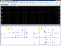
In the asc you posted, the outputs of the regulators with and without the denoiser are labelled with the same name: out.But first let me address the following: I don't think the LTSpice sims work like everybody thinks. Try this:View attachment 806094
The connection between Q6 and C10/12 has been cut. However, it sims just like the version with the connection made. Wierd. The only thing I can come up with is that the network can also work as a shunt between the two power lines, and that this is what the sims show.
However, in my test fixture, cutting this connection has a huge effect.
So, my question to y'all is: did I do something wrong here, and if not, what is going on?
For LTspice, this means that they constitute a single node, ie. they are shorted.
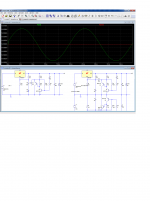
When you unshort them by using different names, things become normal:
Attachments
With a 100ns resolution, everything looks normal: there is a visible residue for the regular 317, which is normal, and nothing is visible for the Dienoiser, which is normal too: in transient mode, the tolerance, digit number and resolution should probably need to be increased to see something.
There is no sign of instability, but the sim is not fully reliable for that: one needs to make a physical test to confirm it, which I did
There is no sign of instability, but the sim is not fully reliable for that: one needs to make a physical test to confirm it, which I did
Attachments
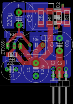
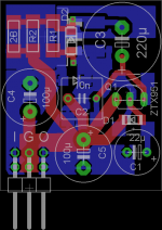
Rotating C5 counter-clockwise by 90° gives some space to connect C4+ to C5+. Just an idea.
Thanks for the help and input. It looks much better to my eye now.
Positive and negative version attached.
The boards will go to the fab this weekend.
Attachments
I use them for a power amp frontend within a cramped case and selfmade adapter boards. Used other LM317 implementations for this before (standard and with tracking pre-reg) and would like to test this one. The amp is a NCC220 from avondale.
With the denoizer on, the noise climbs to .12 uV, but it must be even lower in a well shielded setup. I can see the sort of variations in the noise voltages, .12 was the maximum. And it reacts to presence of a hand or finger like a Theramin, it is very sensitive to EMI. In short, shielding will be important to get the best results.
View attachment 806118
View attachment 806119
Very interesting!!!
A difference of more than 55 dB compared to the regulator alone (without bypass capacitor)!!!.
Could you repeat the measurement by short-circuiting the resistor between base and emitter of the BC560C?
That measurement could help to see the typical differences between the denoiser and the dienoiser.
Best regards
Last edited:
- Home
- Amplifiers
- Power Supplies
- D-Noizator: a magic active noise canceller to retrofit & upgrade any 317-based VReg