That's the startup swing, it's normal. You could also try a 3.6R or 3.9R for R16 in the negative version. For the higher gain versions that resistor was usually needed in my case but in this lower value. 22R is on the high side, don't think I ever used such a high value.
I confirm what Trileru says: the behaviour is normal, and is a result of a trade-off between the VLF correction ability and the capacitors values. If you don't need VLF operation, you can reduce C8. Increasing the 220µ would also be possible, but unpractical unless you absolutely need VLF correction
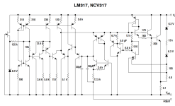
Q1 (+12V rail) has 2.92V (no load, after the swing stops).What's the voltage on collector of Q1/Q3?
Q3 (-12V rail) has -0.99V (no load, there is no swing in this rail).
Aren't they supposed to be the same?
Not really, depends on the gain of BJT with same R3/R18 of 180K. Positive rail has higher swing because of higher Q1 collector voltage. If you increase R18 to 330K for example then the negative startup voltage swing will get higher. At least for the CCS version, not sure how it will work out with R2/R17 instead of CCS.
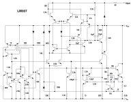
The 337 is a different circuit, designed by another person, and although it was supposed to have a complementary behaviour compared to the 317, things turned out differently.Just out of curiosity, why doesn't the LM337 show the same behavior?
The voltage on Q3 is suspect: check the value of the 180K bias resistor, and the polarity of the 22µ capacitor (+ side connected to the base)
The LM317's series pass device is an NPN transistor operated in common collector mode. However the LM337's series pass device is not a PNP operated in common collector. The LM337 is not a mirror image complement ("dual") of the LM317.
_
_
Attachments

You nailed it. I messed up the resistors (need new glasses) and used a 1K8 instead of a 180K. I completely torn the circuit down and rebuilt it from scratch, double checking all connections and values.The voltage on Q3 is suspect: check the value of the 180K bias resistor, and the polarity of the 22µ capacitor (+ side connected to the base)
Now I get -1.75V at the collector pin of the BC327-40 for a -12.1V stable output voltage (2k ohm load). If I change the output voltage, this value doens't change much. For -5.3V I get 1.57V at Q3 collector pin.
Hello,
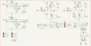
I made this full AC supply from resources on this thread. Can you let me know what you think and maybe what could be done better in terms of layout.
Before you ask, this is fused on other control board.

I made this full AC supply from resources on this thread. Can you let me know what you think and maybe what could be done better in terms of layout.
Before you ask, this is fused on other control board.
Attachments
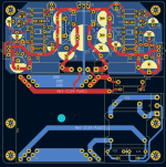
Q3/Q4 GND sense should be closer to C19/C20 Vout sense. Sensing at the output connector can be an issue with planes. Ideally you'd sense at the output connector.
From what i learned here it does not seem that it is necessary but it gives some design flexibility.
Please check your DMQ3/Q4 GND sense should be closer to C19/C20 Vout sense. Sensing at the output connector can be an issue with planes. Ideally you'd sense at the output connector.
Is it possible to design a fixed AC input and multiple voltage values +/- DC outputs?
Transformer is 58 - 0 - 58
Need +48 -48, +12.5, +17 - 17
Transformer is 58 - 0 - 58
Need +48 -48, +12.5, +17 - 17
Last edited:
This is a general question related to this entire thread. With notable exceptions where the circuit designer specifies a specific ESR. Am I free to substitute Aluminum Polymer capacitors for the traditional aluminum electrolytic capacitors? A brief read has uncovered some cost and size advantages.
Here's a brief summary I've read.
Now for the million-dollar question: Are polymer electrolytic capacitors or traditional electrolytic capacitors the better option for engineers? The answer depends on your design needs, as there are unique advantages to each.
Pros of aluminum electrolytic capacitors:
Pros of polymer electrolytic capacitors:
Regards,
Dan
Here's a brief summary I've read.
Comparison of Polymer vs. Traditional Aluminum Electrolytic Capacitors
Now for the million-dollar question: Are polymer electrolytic capacitors or traditional electrolytic capacitors the better option for engineers? The answer depends on your design needs, as there are unique advantages to each.
Pros of aluminum electrolytic capacitors:
- Higher voltage ratings available (up to 600V)
- Way cheaper pricing (for the same capacitance and voltage)
- Better leakage current behavior than polymer
Pros of polymer electrolytic capacitors:
- Lower ESR/higher allowable ripple current
- No dry-out behavior (unlike aluminum capacitors)
- Higher expected lifetime/load life
Regards,
Dan
- Home
- Amplifiers
- Power Supplies
- D-Noizator: a magic active noise canceller to retrofit & upgrade any 317-based VReg