Bump. Thanks!Can someone point me to a schematic of a 5VDC 1.5A supply to power a DAC? It is the initial OVERSHOOT in output voltage that I am concerned about. Thanks.
I found some more info here:
https://electronics.stackexchange.com/questions/18524/resistors-values-to-use-with-lm317
Second answer by user Russell McMahon, mentions that LM317 does have a max of 5uA change in Iadj current. Datasheet mentions this:

With a worst case of 5uA we need to consider max R2 value at needed Vout and allowed Vout change due to this Iadj variation.
So with R1 at 1.2K and Vout of 30V R2 comes out at ~27K. A change of 5uA in this resistor value means some 135mV change in Vout. Depending on application this could matter or not.
The minimum current setup from datasheet does mention it's an up to 20V regulator, with those values.

With R1 1.2K then R2 is 18K at 20Vout which means Vout could vary by a max of 90mV at 20V. Datasheet mentions a minimum of 2.5Vdrop across the regulator so take this into consideration as well, have a healthy 3V minimum if possible.
https://electronics.stackexchange.com/questions/18524/resistors-values-to-use-with-lm317
Second answer by user Russell McMahon, mentions that LM317 does have a max of 5uA change in Iadj current. Datasheet mentions this:
With a worst case of 5uA we need to consider max R2 value at needed Vout and allowed Vout change due to this Iadj variation.
So with R1 at 1.2K and Vout of 30V R2 comes out at ~27K. A change of 5uA in this resistor value means some 135mV change in Vout. Depending on application this could matter or not.
The minimum current setup from datasheet does mention it's an up to 20V regulator, with those values.
With R1 1.2K then R2 is 18K at 20Vout which means Vout could vary by a max of 90mV at 20V. Datasheet mentions a minimum of 2.5Vdrop across the regulator so take this into consideration as well, have a healthy 3V minimum if possible.
Last edited:

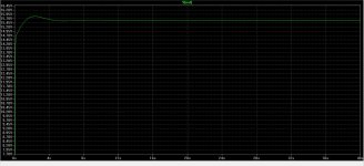
@carlmart On the schematic from post #3114 change LED R15 to 3.9K, R14 can be 300K-330K, C8 10uF, C11 3.3uF and R17 100K. See if the spike is lower with these values.
It certainly improved.
Attachments
I couldn't find other better 317 models.
Running current demand will be very low, as it powers a RIAA preamp with two low current ICs per channel. Probably won't even need a heatsink on the regulators.
Running current demand will be very low, as it powers a RIAA preamp with two low current ICs per channel. Probably won't even need a heatsink on the regulators.
Rickth has experimented with even higher values, to make a low-power version, and he didn't seem to have encountered particular problemsI found some more info here:
https://electronics.stackexchange.com/questions/18524/resistors-values-to-use-with-lm317
Second answer by user Russell McMahon, mentions that LM317 does have a max of 5uA change in Iadj current. Datasheet mentions this:
View attachment 1378140
With a worst case of 5uA we need to consider max R2 value at needed Vout and allowed Vout change due to this Iadj variation.
So with R1 at 1.2K and Vout of 30V R2 comes out at ~27K. A change of 5uA in this resistor value means some 135mV change in Vout. Depending on application this could matter or not.
The minimum current setup from datasheet does mention it's an up to 20V regulator, with those values.
View attachment 1378146
With R1 1.2K then R2 is 18K at 20Vout which means Vout could vary by a max of 90mV at 20V. Datasheet mentions a minimum of 2.5Vdrop across the regulator so take this into consideration as well, have a healthy 3V minimum if possible.
View attachment 1295832
PSRR:
View attachment 1295833
Overshot:
View attachment 1295834
Thermal drift:
View attachment 1295835
Best regards
I simulated both Diego circuits above, and they seem to work flawlessly.
I want to power up two Topping DACs - E50 and D50s. Thanks.What DAC chip?
1.2K seems fine for some performance boost with the Denoisator. May make sense to increase R1 so you get closer to 120dB of PSRR with lower Vout, like 5V.Rickth has experimented with even higher values, to make a low-power version, and he didn't seem to have encountered particular problems
I think C12 from previous post 5V schematic would fail safe. The lower in value it goes (degrading in time) the less the startup spike, but also eats into LF performance.I want to power up two Topping DACs - E50 and D50s. Thanks.
edit:
Unless it somehow shorts out, in which case you'll have a higher startup spike. Even so you should measure this worst case scenario spike, in practice. Some 5V devices are max 5.25V rated for continuous operation but do have 6V absolute maximum rating for a short while, before they start degrading. Check the datasheets.
Last edited:
There is a DC path between denoiser and ADJ pin so tempco will take a small hit. Run a temperature sweep.I simulated both Diego circuits above, and they seem to work flawlessly.
Between 25 and 75 °C, the output voltage drift is less than 24 mV, comparable to one of your designs.
The attractive thing about the one simulated by Carlos is that it does not show that annoying initial voltage overshoot.
Even by conveniently choosing C3 (or C333, depending on the scheme), R5 (or R55, depending on the scheme) could be deleted. Something like 1000 uF would be fine for both, while the base current of Q (or Q1, depending on the scheme) would be at admissible values.
View attachment 1295832
PSRR:
View attachment 1295833
Overshot:
View attachment 1295834
Thermal drift:
View attachment 1295835
Best regards
I ran a sweep for 1K to 4.7K for R1 and there are good gains. Here's a comparison to NoNoiser PSRR at 15Vout:Rickth has experimented with even higher values, to make a low-power version, and he didn't seem to have encountered particular problems
Problem is at 4.7K there's 265uA through the resistor chain, 5uA variation in Iadj throws off Vout by 258mV. 3.3K comes out at 180mV variation for 5uA Iadj. I think 2.7K is an upper limit. And maybe not for higher than 12Vout.
If precision is not important then even 4.7K might work.
edit: Past 3.3K there's diminishing returns in PSRR gain. There's 5dB to NoNoiser performance.
Output impedance is already similar to NoNoiser even at 3.3K.
Last edited:
@diegomj1973 Fully AC coupled there should be less than that:

But in the grand scheme of things sure, 24mV is not a lot.
Also keep your R5 if you're not in noise measurement contest. At 33R it has similar noisefloor to the whole regulator without it. But could protect the denoiser BJT in some situations.
But in the grand scheme of things sure, 24mV is not a lot.
Also keep your R5 if you're not in noise measurement contest. At 33R it has similar noisefloor to the whole regulator without it. But could protect the denoiser BJT in some situations.
If you run a bit more current through your second design you can get closer to 120dB, at least with my models. Tempco should get a bigger hit but still no startup spike, and some 3.3mA through the denoiser.

Good news! I've been testing this latest version, with 2.7K for R1, and I managed to get both LM317 and LM337 stable.
LM317 is easy, 22nF comp cap and any 0.2R ESR cap. I managed to also have it stable with 2x22uF 0805 ceramic caps in parallel + 0.2R in series (ignore the 1R in photo I was testing limits).
The way I tested was with an electronic load with a load profile similar to this:

I set a sine load of 300mApp on top of 100mA static at some 1-2Hz. This + tapping on the base of denoiser BJT seemed like the most I could do to upset the denoiser.
LM317 was pretty rock solid I couldn't get it to budge. It does vary some 10mV with the load, but when it's unstable I only need to tap the base a few times and it goes wild.
For LM337 I also used a resistor in series with comp cap. I remembered Elvee saying he used 3.9R to get LM337 Denoisator stable so I used 3.6R + 22nF in my case. But this isn't enough. Output cap clearly needs some extra inductance. I tried all combinations without it, it's not stable without it.
It might seem stable without a load, or even with a load but when tapping the base it goes into oscillation. But with that inductor I can't get it to budge either way.
I even managed to get it stable with 2x22uF 0805 ceramics + 0.2R + inductor. It was quite stable just like with larger electrolytics. I also tested a polymer cap, didn't work unless I added 0.2R + inductor. ESR can be similar to LM317 output, 0.2-0.3R seems to work fine. 0.018R/0.040R didn't work, I had to add 0.2R in series and it worked.
The inductor was made from some thin enameled wire, 4cm long. Doesn't matter if it's coiled or a single loop, works just the same.

(cap in photo is Panasonic FP 0.16R ESR, worked fine with just inductor)
If cap is not too low ESR it only needs this piece of wire and should be stable.
Also if anyone who's having issues with LM337 Denoisator could confirm this it would be great. Just use some 0.2-0.3R ESR cap, 100uF should be fine. And add the equivalent of 4cm of the wire in the photo (and 22nF-33nF + 3.3R-3.9R for denoiser comp). Don't know its thickness my calipers aren't precise down there. I coiled it up on the tip of my tweezers some 5 turns and worked fine like that.
Yet to look at AC that will happen later on I'm still waiting for some parts.
Ah yes I forgot, I looked at both Vout and denoiser collector. Vout hides some denoiser activity so it's best to keep an eye on the collector, it's more revealing to stability than Vout.
Also cold starts directly under load are a good test for stability.
LM317 is easy, 22nF comp cap and any 0.2R ESR cap. I managed to also have it stable with 2x22uF 0805 ceramic caps in parallel + 0.2R in series (ignore the 1R in photo I was testing limits).
The way I tested was with an electronic load with a load profile similar to this:
I set a sine load of 300mApp on top of 100mA static at some 1-2Hz. This + tapping on the base of denoiser BJT seemed like the most I could do to upset the denoiser.
LM317 was pretty rock solid I couldn't get it to budge. It does vary some 10mV with the load, but when it's unstable I only need to tap the base a few times and it goes wild.
For LM337 I also used a resistor in series with comp cap. I remembered Elvee saying he used 3.9R to get LM337 Denoisator stable so I used 3.6R + 22nF in my case. But this isn't enough. Output cap clearly needs some extra inductance. I tried all combinations without it, it's not stable without it.
It might seem stable without a load, or even with a load but when tapping the base it goes into oscillation. But with that inductor I can't get it to budge either way.
I even managed to get it stable with 2x22uF 0805 ceramics + 0.2R + inductor. It was quite stable just like with larger electrolytics. I also tested a polymer cap, didn't work unless I added 0.2R + inductor. ESR can be similar to LM317 output, 0.2-0.3R seems to work fine. 0.018R/0.040R didn't work, I had to add 0.2R in series and it worked.
The inductor was made from some thin enameled wire, 4cm long. Doesn't matter if it's coiled or a single loop, works just the same.
(cap in photo is Panasonic FP 0.16R ESR, worked fine with just inductor)
If cap is not too low ESR it only needs this piece of wire and should be stable.
Also if anyone who's having issues with LM337 Denoisator could confirm this it would be great. Just use some 0.2-0.3R ESR cap, 100uF should be fine. And add the equivalent of 4cm of the wire in the photo (and 22nF-33nF + 3.3R-3.9R for denoiser comp). Don't know its thickness my calipers aren't precise down there. I coiled it up on the tip of my tweezers some 5 turns and worked fine like that.
Yet to look at AC that will happen later on I'm still waiting for some parts.
Ah yes I forgot, I looked at both Vout and denoiser collector. Vout hides some denoiser activity so it's best to keep an eye on the collector, it's more revealing to stability than Vout.
Also cold starts directly under load are a good test for stability.
Of course your version is different than Elvee's original denoiser , but the issue I had with LM337 , is that it couldn't take ceramics (>=1uF) directly at its output. And you put 2x22uF ?
I must admire your determination though , that you are still with it after nearly 6 years ....
I must admire your determination though , that you are still with it after nearly 6 years ....
It should work with the original Denoisator. I think I noticed the extra inductance thing before coming up with the CCS. But seems required for LM337, LM317 works fine without it (ceramics + series resistor), at least on my board. LM337 needs the inductor no matter if ceramics or electrolytic. And 3.3R-3.9R in series with comp cap (22nF-33nF).
Somewhat works without it but if I tap the base of BJT while under load I can get it to swing bad, hits the rail, drops to 0 then comes back. So it might work but doesn't seem as stable as with the inductor.
Somewhat works without it but if I tap the base of BJT while under load I can get it to swing bad, hits the rail, drops to 0 then comes back. So it might work but doesn't seem as stable as with the inductor.
- Home
- Amplifiers
- Power Supplies
- D-Noizator: a magic active noise canceller to retrofit & upgrade any 317-based VReg