Ok , at last ... my experience with LV's DeNoiser.
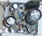
Finally my components arrived and I could start testing. 2 x 15 V transformer 7,5 VA , just rectify and a 1000µF cap : 240mV rimple at around 115 mA load , with 4700µF , it went down to 55mV... still too much . So and CRC with 12 ohm after the 4700µ and a 1000µ : rimple 7mV.
7mV rimple is loud in a HP.
Standard LM317 + Cadj 22µF , and far below 1 mV ... steady 000mV om my Fluke DVM. Having no measuring equipment , I use the unscientific method of my ears. Put a 100µ Cap on the 15 V output , discharched it and connected the headphone ... nothing to hear.
(btw : if you do this you may fry your HP if there is a DC difference between the Cap and the 0. So use "disposable" HP's ! )
As a side note : I made white noise in Audacity 96khz 32 bit , full on 0 dB , then attenuated it to -80 dB and with volume on max this is clearly audible, even at -90 dB , -95 dB was my limiet that I could hear. In a fully quiet room -100 dB was not audible , but it could be the limits of my laptop's audio chips. These have +-2 V max output ( 4Vpp) , so 100 dB = 40 µVpp = 7µVrms is not audible . The Denoiser is 0,33µVrms ... according to LV.
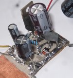
Now LV's DeNoiser :
Again nothing with the headphones , no surprise there. I did see the start up , it takes about 23 sec to get full stability on the right voltage after meandering above and below the 15 V output.
But to all this there is a cost : I thought LV said something about that it consumes as much as the regulator LM317 , and I took that as : the whole circuit consumes the same , my mistake . It actually doubles the whole regulators working current . Running without load goes from 6 mA to 12 mA (because I didn't have 220 ohm , I put 2 x 100 ohm , so for 220 ohm it wil be slightly less , 11 mA or so). It gets worse , because of the base current of the LM's output transistor , this goes to about 17 mA with a 100 mA load ...! Quite a lot . (not the DeNoiser's fault of course) . I wanted to use 4 of them ... + & -15 V and L & R , that's 70 mA just for the regulators ! (at 100 mA out)
Remember a lot of posts ago , I said those expensive low noise LDO's from T.I and LT would be redundent for audio with LV's DeNoiser, well they weren't . Not just low drop but also lower quiescent current than the LM317 + DeNoiser.
6 mA more is not dramatic , of course . But the transformer I just bought ( 2 x 15 V) , gives me 21,5 V at 100 mA out ! So I get it from both sides , higher current , and around 6 or 7 V over the LM317/337 (depending on the 10 ohm R in the CRC) , so with 17 mA extra over an 100mA output current , that's > 700 mW .... so no cute DPAK for me , but a cooled TO220. Yes I could put some diodes in there to lower the voltage or even a Capacitance multiplier .
I don't know why the transformer gives me 21,5 V /side at 100 mA , maybe order an 2 x 12 V one ? I first put the 1N5822 Schottky's as rectifiers , they only go to 40 V ...they got around 50 with no load ... they didn't break though....
While lower noise is great , the question is : if I can't hear it the LM317/337 + C adj , is it worth another 6-7 mA for the DeNoiser ?
What was a (welcome) sure thing for my upcoming HP amp , I'm not sure now if I'm going to use it. Maybe I should test out the expensive and for me hard to get T.I and L.T's , although with 6 V to waste , a low drop regulator is stupid. Or I could just stay with the standard LM +Cadj.
Some numbers : with Vout = 15 V , transistor's collector 4,55 V , base 630 mV , both not changing with load.
Finally my components arrived and I could start testing. 2 x 15 V transformer 7,5 VA , just rectify and a 1000µF cap : 240mV rimple at around 115 mA load , with 4700µF , it went down to 55mV... still too much . So and CRC with 12 ohm after the 4700µ and a 1000µ : rimple 7mV.
7mV rimple is loud in a HP.
Standard LM317 + Cadj 22µF , and far below 1 mV ... steady 000mV om my Fluke DVM. Having no measuring equipment , I use the unscientific method of my ears. Put a 100µ Cap on the 15 V output , discharched it and connected the headphone ... nothing to hear.
(btw : if you do this you may fry your HP if there is a DC difference between the Cap and the 0. So use "disposable" HP's ! )
As a side note : I made white noise in Audacity 96khz 32 bit , full on 0 dB , then attenuated it to -80 dB and with volume on max this is clearly audible, even at -90 dB , -95 dB was my limiet that I could hear. In a fully quiet room -100 dB was not audible , but it could be the limits of my laptop's audio chips. These have +-2 V max output ( 4Vpp) , so 100 dB = 40 µVpp = 7µVrms is not audible . The Denoiser is 0,33µVrms ... according to LV.
Now LV's DeNoiser :
Again nothing with the headphones , no surprise there. I did see the start up , it takes about 23 sec to get full stability on the right voltage after meandering above and below the 15 V output.
But to all this there is a cost : I thought LV said something about that it consumes as much as the regulator LM317 , and I took that as : the whole circuit consumes the same , my mistake . It actually doubles the whole regulators working current .
Running without load goes from 6 mA to 12 mA (because I didn't have 220 ohm , I put 2 x 100 ohm , so for 220 ohm it wil be slightly less , 11 mA or so). It gets worse , because of the base current of the LM's output transistor , this goes to about 17 mA with a 100 mA load ...! Quite a lot . (not the DeNoiser's fault of course) . I wanted to use 4 of them ... + & -15 V and L & R , that's 70 mA just for the regulators ! (at 100 mA out)Remember a lot of posts ago , I said those expensive low noise LDO's from T.I and LT would be redundent for audio with LV's DeNoiser, well they weren't . Not just low drop but also lower quiescent current than the LM317 + DeNoiser.
6 mA more is not dramatic , of course . But the transformer I just bought ( 2 x 15 V) , gives me 21,5 V at 100 mA out ! So I get it from both sides , higher current , and around 6 or 7 V over the LM317/337 (depending on the 10 ohm R in the CRC) , so with 17 mA extra over an 100mA output current , that's > 700 mW .... so no cute DPAK for me , but a cooled TO220. Yes I could put some diodes in there to lower the voltage or even a Capacitance multiplier .
I don't know why the transformer gives me 21,5 V /side at 100 mA , maybe order an 2 x 12 V one ? I first put the 1N5822 Schottky's as rectifiers , they only go to 40 V ...they got around 50 with no load ... they didn't break though....
While lower noise is great , the question is : if I can't hear it the LM317/337 + C adj , is it worth another 6-7 mA for the DeNoiser ?
What was a (welcome) sure thing for my upcoming HP amp , I'm not sure now if I'm going to use it. Maybe I should test out the expensive and for me hard to get T.I and L.T's , although with 6 V to waste , a low drop regulator is stupid. Or I could just stay with the standard LM +Cadj.
Some numbers : with Vout = 15 V , transistor's collector 4,55 V , base 630 mV , both not changing with load.
Attachments
Last edited:
While lower noise is great , the question is : if I can't hear it the LM317/337 + C adj , is it worth another 6-7 mA for the DeNoiser ?
Depends upon the application. Clocks need very low noise power sources. Preamplifiers, particularly moving coil ditto.
Not only does the circuit have very low noise, it also has very low output impedance and very good PSRR. The LM317+Cap is rather mediocre in all these respects.
And if you've got the voltage headroom, you can connect N of them in series for a theoretical N-fold increase in dB's of line rejection ("PSRR").
At 11 mA a piece , putting a lot of them in series , a bit much.
The first thing I thought of when I saw the DeNoiser was, why is LV using 220 ohm to set the current ? I 've used the LM317 with as high as 1k2 , well , not for audio though . I think he did it for resistor noise (especially the one from the adjust to the ground), maybe low impedance .
With the resistor values given , if it works for low output voltages like 5V , so why why not change the 1k8 resistor three times as high for 15 volts ?
So here are my idea's for tweaking the DeNoiser :
Instead of the 220 ohm , 470 ohm or even 560 , this would change the quiescent current to 2,6 mA or 2,2 mA , changing the voltage set R in 5k2 or 6k2 for 15 V.
Change the 1k8 going to the collector to 5k6 . This would bring down the current to 1,8 mA . Total current would come down to around < 4,4 mA from 11 mA now. Of course the 5mA base current for the LM's output transistor (for 100mA load) , would stay the same. Added bonus is that the dissipation of the 5k2/6k2 and 5k6 would be lower so you can use SMD resistors which makes it a little more compact to build.
I have no idea how this will affect the noise attenuation , PSRR and output impedance though.
Oh , and yes I realize that the base current flows through the load , so not wasted .
Last edited:
When I build projects that need the lowest possible supply noise, I use R-core transformers such as these:
30W 24V+24V
HiFi Audio parts Sotre>>Amplifier kit > Tube Preamp > DAC kit >>shipping to worldwide
They have plenty of excess current rating, which very comfortably allows investing an additional ~ 33mA in cascades of voltage regulators. These R-cores also provide plenty of voltage headroom to support the necessary (Vin - Vout) "dropout voltage" across each regulator stage.
(remember that after bridge rectifiers and filter caps, a 2x24VAC transformer gives you ~ ±31VDC and an 2x18VAC transformer gives you ~ ±22VDC)
_
Last edited:
Hang a 20mA load (resistor) on the final regulated voltage. Call it a bleeder if you wish. This 20mA flows through the entire series cascade of regulators and/or capacitance multipliers and/or ripple eaters and/or Magic Cancellers, making them all very happy.
Rbleed = FinalRegulatedVoltage / 0.02
WattageRatingOfRbleed >= 4 * RegulatedVoltage * 0.02
Rbleed = FinalRegulatedVoltage / 0.02
WattageRatingOfRbleed >= 4 * RegulatedVoltage * 0.02
It certainly is, but the basic 317 + caps already reduces that by several tens of dB, and the denoiser adds more than 30dB on top of that.Ok , at last ... my experience with LV's DeNoiser.
Finally my components arrived and I could start testing. 2 x 15 V transformer 7,5 VA , just rectify and a 1000µF cap : 240mV rimple at around 115 mA load , with 4700µF , it went down to 55mV... still too much . So and CRC with 12 ohm after the 4700µ and a 1000µ : rimple 7mV.
7mV rimple is loud in a HP.
Can you start with 70mV? Almost certainly.
Can you start with 700mV? Possibly
The nonoiser has significantly higher performance, and consumes as a whole (317 + nonoiser) the same as a regular 317.Now LV's DeNoiser :
Again nothing with the headphones , no surprise there. I did see the start up , it takes about 23 sec to get full stability on the right voltage after meandering above and below the 15 V output.
But to all this there is a cost : I thought LV said something about that it consumes as much as the regulator LM317 , and I took that as : the whole circuit consumes the same , my mistake . It actually doubles the whole regulators working current .
If you build it from scratch and not as an upgrade, it is a possibility (but you need good construction techniques to benefit from the lower noise and higher performance)
That sounds spot on.....I don't know why the transformer gives me 21,5 V /side at 100 mA ,
The decision is entirely yours: I do not push anyoneWhile lower noise is great , the question is : if I can't hear it the LM317/337 + C adj , is it worth another 6-7 mA for the DeNoiser ?
What was a (welcome) sure thing for my upcoming HP amp , I'm not sure now if I'm going to use it. Maybe I should test out the expensive and for me hard to get T.I and L.T's , although with 6 V to waste , a low drop regulator is stupid. Or I could just stay with the standard LM +Cadj.
No, it is just to remain in the upgrade spirit: most existing regs will have these values, to satisfy DC stability criterions.The first thing I thought of when I saw the DeNoiser was, why is LV using 220 ohm to set the current ? I 've used the LM317 with as high as 1k2 , well , not for audio though . I think he did it for resistor noise (especially the one from the adjust to the ground), maybe low impedance .
If you feel you can relax the temperature stability, why not?
The nonoiser sacrifices the DC stability from the start, but it is once and for all: the buffer transistor eliminates 317-related sources of instability
Why not, if you do not need DC stability?So here are my idea's for tweaking the DeNoiser :
Instead of the 220 ohm , 470 ohm or even 560 , this would change the quiescent current to 2,6 mA or 2,2 mA , changing the voltage set R in 5k2 or 6k2 for 15 V.
Change the 1k8 going to the collector to 5k6 . This would bring down the current to 1,8 mA . Total current would come down to around < 4,4 mA from 11 mA now. Of course the 5mA base current for the LM's output transistor (for 100mA load) , would stay the same. Added bonus is that the dissipation of the 5k2/6k2 and 5k6 would be lower so you can use SMD resistors which makes it a little more compact to build.
I have no idea how this will affect the noise attenuation , PSRR and output impedance though.
Oh , and yes I realize that the base current flows through the load , so not wasted .
Otherwise, opt for the nonoiser, and you will not even have to worry with the initial ripple....
Math error---40µV p-p = 14.14µV rms, not 7......... the limits of my laptop's audio chips. These have +-2 V max output ( 4Vpp) , so 100 dB = 40 µVpp = 7µVrms is not audible .
Probably still not audible.
Last edited:
There is probably a misconception there: most of the standing current of the 317 is absorbed by the divider, and does not go into the load, it is in fact subtracted from the load.Oh , and yes I realize that the base current flows through the load , so not wasted .
The "base" (if you call it that) current of the 317 is about 50µA, and relatively constant (but not perfectly, which is why the divider current needs to be much higher).
The morality of all that is, overkill kills: you are not going to use a formula-1 car for your home-work commuting, and similarly, you should not use an over-engineered solution for a mundane problem (or worse: a non-problem)
Some applications benefit from a better supply, even as a retrofit, because at the time of the design, optimal solutions didn't exist or were too costly, but the suitability of an upgrade should be judged on a case by case basis (I know it's not in the audiophile ADN, but it is the sensible method)
Ignore my remarks on the base current and more current consumption with bigger loads. I tested these inconsistencies twice before I remembered that my DVM has a 5,2 ohm resistor in series on the 300 mA range . Duh !! While that doesn't matter measuring the whole regulator , it does matter in series with the load R's on the output.
As for the pp to rms : I researched that a while ago , and it was 6,6 times . Looking at it again , here's one that says 8 times :
Relationship between RMS noise and peak-to-peak noise
But you're right too , dotneck335:
V peak to peak to Vrms conversion calculator
When we talk about random noise , numbers get a little fuzzy...
The Nonoiser is more complex , bigger (too many components) and needs kelvin connection , that's why I pass on it . Besides , I see the R2 of 1k5 going to the transistor again , which suggests even more quiescent current than the DeNoiser.
So the changes I suugested would only deteriorate DC stability ?
Like temperature of the LM changes the output voltage ?
When the LM heats up , I measure about 20 mV more on the output with the DeNoiser.
But does the noise , PSSR stay the same ?
What about the 180k and the 47 ohm resistor , I guess they don't matter much , when there is no change using a transistor with high or lower hfe.
When I build projects that need the lowest possible supply noise, I use R-core transformers such as these:
30W 24V+24V
HiFi Audio parts Sotre>>Amplifier kit > Tube Preamp > DAC kit >>shipping to worldwide
They have plenty of excess current rating, which very comfortably allows investing an additional ~ 33mA in cascades of voltage regulators. These R-cores also provide plenty of voltage headroom to support the necessary (Vin - Vout) "dropout voltage" across each regulator stage.
(remember that after bridge rectifiers and filter caps, a 2x24VAC transformer gives you ~ ±31VDC and an 2x18VAC transformer gives you ~ ±22VDC)
_
When I listen to the transformer 's retified output , there is no noise , just the 100 hz hum and some very minor rattling . That's why Elektor put 10nF over the rectify diodes. After the CRC filter there is only a small 100 hz hum.
I knew that rectified votage is higher than the rated voltage of the transformer , I just didn't expect 25 V from 15 V . In the past I used toroidal transformers and they didn't get this high . That's why used Schottky's the first time.
That's why Elektor put 10nF over the rectify diodes. After the CRC filter there is only a small 100 hz hum.
No, that is not why Elektor put 10nF caps over the rectifiers.
Their purpose is to damp the ringing which arises from the leakage inductance and the capacitance of the rectifiers.
If you don't see ringing when looking at the rectified output of the power supply with an oscilloscope, they aren't necessary. (Pic below is an extreme example.)
Attachments
^ As an avid reader of Elektor , (well in the 80's and 90's at least) , I distictly remember them writing that is was for rattling of the rectifier diodes . Maybe that is caused by the ringing or it was their second motive for using those caps .
I don't have enough time to go through all the Elektors to find proof , and it would be in another language than English.
I don't have enough time to go through all the Elektors to find proof , and it would be in another language than English.
^ As an avid reader of Elektor , (well in the 80's and 90's at least) , I distictly remember them writing that is was for rattling of the rectifier diodes . Maybe that is caused by the ringing or it was their second motive for using those caps .
I don't have enough time to go through all the Elektors to find proof , and it would be in another language than English.
Read this thread: Simple, no-math transformer snubber using Quasimodo test-jig
The correction amplifier does indeed use a similar or slightly higher current, but the buffer transistor practically eliminates the 317-related consumption, with a degradation limited to the mismatch between the transistor and the compensating diode (thus very weakly current-dependent)Besides , I see the R2 of 1k5 going to the transistor again , which suggests even more quiescent current than the DeNoiser.
No, only the DC stability is affected (and perhaps VVLF noise, below 1Hz or so).So the changes I suugested would only deteriorate DC stability ?
Like temperature of the LM changes the output voltage ?
When the LM heats up , I measure about 20 mV more on the output with the DeNoiser.
But does the noise , PSSR stay the same ?
What about the 180k and the 47 ohm resistor , I guess they don't matter much , when there is no change using a transistor with high or lower hfe.
The resistors of the correction amplifier have no effect whatsoever on the DC stability, because of the AC coupling.
I doubt you could hear any rattling directly: the effect of the caps is twofold: it lowers the ringing frequency induced by the diodes, which could have an effect on the surrounding circuits (but only on the AC side) because capacitive coupling is weaker for lower frequencies, and more importantly, it "normalizes" their impedance for high frequencies.^ As an avid reader of Elektor , (well in the 80's and 90's at least) , I distictly remember them writing that is was for rattling of the rectifier diodes . Maybe that is caused by the ringing or it was their second motive for using those caps .
I don't have enough time to go through all the Elektors to find proof , and it would be in another language than English.
In a poorly laid out circuit, lowering the ringing resonance from a MHz or two to tens of kHz could ease problems, but the best solutions are either not to depend on the cleanliness of an inherently dirty source (the mains), or to to clean it up completely, using Mark's solution for example.
The two options are not mutually exclusive (but low coupling from mains interference is the first thing to consider anyway).
Diodes can cause other troubles (probably more frequent): they act as PIN diodes or modulators, meaning they can disrupt radio reception with a 100Hz buzz, or modulate conducted interference in the same way, with somewhat similar effects: see my thread about the Cancellator, where this kind of interference is clearly modulated (by the SMPS own diodes, but any diode of a linear supply will also behave in the same way).
However, none of the above applies to direct, differential mode effects on the ripple, meaning you shouldn't hear any rattling, especially with a direct, passive listening device.
They could have a marginal effect on an active device (signal-tracer f.e.) via envelope rectification.
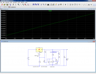
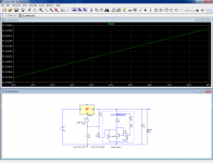
Here are the sims you asked for: first, the temperature stability of the initial circuit:
It looks rather optimistic, in particular the parabolic T° dependence does not seem to be modelled.
Anyway, here is the the modified circuit in the same conditions (I also changed the collector load, even though it has no effect):
As you can see, the difference is anecdotal, but the reality is probably somewhat different (though not much worse)
Attachments
The main resistor acting on the output voltage is R5, so we can rewrite the expression to yield R5:
R5 = (R3*(Vout-Vref-Vbe)+R8*(Vout/2+Vd/2-Vref-Vbe))/(Vref-Vd+Vbe)
or R5 ~= (Vout* 7600) - 15800
Thanks LV. You took it one step further with 680 & 6k8 , so around 3,3 mA instead of the 11-ish of the original. Battery operated devices will be pleased . I wasn't worried of the tempco of the DeNoiser , it doesn't matter much with regulators for audio amps . And even with 680 ohm , line and load regulation will not suffer much especially with loads up to only 200 mA , not the 1,5 A as specified maximum current of the LM317/337.
Most interesting will be whether there is a change in noise reduction between the normal version and the low quiescent current one.
"I doubt you could hear any rattling directly" .
Well I did hear some very faint rattling , but it was gone after the CRC so now I'm not sure if I'm going to use the 22nF I already bought to put over the diodes. I use ultra fast diodes , just because I can and they're cheap.
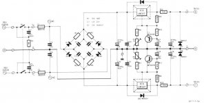
Here's one from Elektor 86 's preamp, I think . Notice the big 4700uF cap after the LM. I could be wrong but I still trust Elektor more than some on a forum.
Most interesting will be whether there is a change in noise reduction between the normal version and the low quiescent current one.
"I doubt you could hear any rattling directly" .
Well I did hear some very faint rattling , but it was gone after the CRC so now I'm not sure if I'm going to use the 22nF I already bought to put over the diodes. I use ultra fast diodes , just because I can and they're cheap.
Here's one from Elektor 86 's preamp, I think . Notice the big 4700uF cap after the LM. I could be wrong but I still trust Elektor more than some on a forum.
Attachments
Last edited:
Nice!LV mini
In fact no, the screenshot from LTspice distorts the figures, and I used your 6K2/560 values (but it does not really matter).Thanks LV. You took it one step further with 680 & 6k8 , so around 3,3 mA instead of the 11-ish of the original.
If the collector load is also changed, the base 180K should of course be scaled ~accordingly (and also the cap values)
The differences will be very minorMost interesting will be whether there is a change in noise reduction between the normal version and the low quiescent current one.
,"I doubt you could hear any rattling directly" .
Well I did hear some very faint rattling
It depends on the definition of "rattling": the sawtooth of the ripple has a significant harmonic content, but does it qualify?
That's a brute force approach, and it works of course, at least for noise and ripple, but the output impedance and the regulation are seriously degradedHere's one from Elektor 86 's preamp, I think . Notice the big 4700uF cap after the LM. I could be wrong but I still trust Elektor more than some on a forum.
- Home
- Amplifiers
- Power Supplies
- D-Noizator: a magic active noise canceller to retrofit & upgrade any 317-based V.Reg.