Yes , I like slow start up , although 110 sec seems long but doable for getting these noise numbers but we might have to wait 2 minutes to engage the output relay . Is the DeNoiser this slow too ?
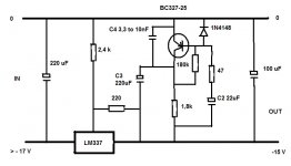
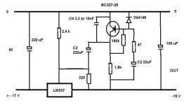
LV hasn't showed the LM337 + DeNoiser , so I'll do it .
Some questions again before I order :
C2 : 22 uF elco , tantalum or even X7R ceramic ?
C4 : 3,3 nF to 10 n or even 22 nF , again X7R (NP0 ) or MKT/P ?
What is best ?
LV hasn't showed the LM337 + DeNoiser , so I'll do it .
Some questions again before I order :
C2 : 22 uF elco , tantalum or even X7R ceramic ?
C4 : 3,3 nF to 10 n or even 22 nF , again X7R (NP0 ) or MKT/P ?
What is best ?
Attachments
Last edited:
Denoiser is a lot faster. I haven't made simulation myself but on some other forum some guy made lab supply based on LM317 with added denoiser,made simulations and build it and startup time was a lot faster i think around 5-10 secs.
About adding relay ofc i thought about it, it would be pretty much simple and easy solution.
About adding relay ofc i thought about it, it would be pretty much simple and easy solution.
No, as Khadgar remarked, it is much faster (relatively speaking): about 15 seconds:Yes , I like slow start up , although 110 sec seems long but doable for getting these noise numbers but we might have to wait 2 minutes to engage the output relay . Is the DeNoiser this slow too ?
That's a perfect complementary translation, exactly what I would have done.LV hasn't showed the LM337 + DeNoiser , so I'll do it .
Will it actually work? I am inclined to think so, but only one test could conclusively prove it: reality
With the 47 ohm protection in series, it doesn't matter at all: opt for the cheapest EcapSome questions again before I order :
C2 : 22 uF elco , tantalum or even X7R ceramic ?
With the benefit of hindsight, I would recommend 10 or 22nF, X7R, and a series 33 ohm could also help.C4 : 3,3 nF to 10 n or even 22 nF , again X7R (NP0 ) or MKT/P ?
What is best ?
Don't be afraid to experiment, nothing is going to be damaged
Attachments
Don't be afraid to experiment, nothing is going to be damaged
Sure , but if you don't have measuring equipment , how can you tell the difference .
The startup of the DeNoiser looks good to me (<3 secs) . Just the slow 16 V peak is something to watch out for if you use over voltage protection/detection like I do . (zeners/transient voltage suppressor diodes)
The PNP of the ZTX851 seems to be ZTX951 , for lowest noise .
Or if you like them small : BC337 = BC817 and BC327= BC807 in smd.
Last edited:
About "poor man denoiser "
With LT1963, a simple cap is used to reduce noise to 32nV/sqrt Hz
Is this principe can be used with LT1763 also ?
What would be the expected benefits ?
Thanks !
LT1963 will only take 20V, and is an LDO so that the output smoothing capacitor is in the feedback loop. FWIW, it ranked pretty well in the Linear Audio regulator shootout.
If the wiring is correct (which is not difficult considering the simplicity) and there are no unwanted oscillations, the circuit will work as intended.Sure , but if you don't have measuring equipment , how can you tell the difference ..
So, the question is how to detect parasitic oscillations without equipment.
An old trick is to place an AM radio in the vicinity: it should pickup oscillations.
Another option is to use a sniffer probe used with a multimeter:
Oscillation Sniffer
You can also observe the DC output voltage when you connect the denoiser (C3): if there is a permanent shift, it probably means instabilities.
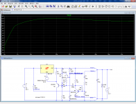
Here is a "fast" version of the nonoiser: the output voltage becomes usable after ~10s.
The 1V overshoot remains present
Attachments
Here is a virtual evaluation of the LT1763: the denoiser brings a modest improvement compared to the regular bypass cap: from 23nV/√Hz to 7nV/√Hz.And a "poor man denoiser" can be also coupled with LT1763 ?
Because LT1763 has originally less noise than LT1963
Note that the denoiser and the bypass cap should not be used together: the bypass cap defeats the denoiser, rendering it useless
Attachments
and there are no unwanted oscillations, the circuit will work as intended
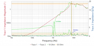
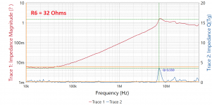
You might want to consider a different value than 10R for R6 -- this is one I built from the schematic with 100u/10R. The graph below shows a Q peak of ~6.9 at 1.5MHz -- phase margin less than 9 degrees. With 50R, Q is 1.7 and PM is around 31 degrees.
I didn't see this behavior in LTSpice simulation w LTSpice.
R6 will affect noise performance.
Attachments
I didn't see this behavior in LTSpice simulation w LTSpice.
I would have sided with LTspice on that: 50 ohm with Cbe and Cbc in the 10pF range implies time constants of ~500ps, meaning the effect if any should manifest itself well in the VHF range, not 1.5MHz.
In addition, the effect of the resistance should be swamped by the transformed impedance of the ferrite bead in the emitter.
Of course, the reality is immune to that kind of sensible reasoning, and it has to have the last word....
With this kind of circuit, the devil is in the details, even the tiniest ones: when I made my frequency sweep, I didn't pay a great attention to the injection point, and I found impedance quirks.
When I adopted a more deterministic approach and moved the injection point ~2cm, all the oddities vanished.
A detective work is probably required to determine exactly what the cause of this anomaly is.
50 ohm will severely degrade the noise performance if the transistor is a ZTX851. Even 10 ohm is already borderline.
I didn't intend R6 as a base-stopper but as a base protection in case of transients.
If it has to work as a base stopper, and what's more in the wrong frequency range, there is definitely something fishy somewhere
Perhaps it is a bit more clear to separate the charts into two examples -- I was using a BC337-25, switched to a ZTX851 for the purpose of this experiment. As mentioned, I don't see this behavior in simulation, but do see it on the workbench:
Attachments
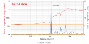
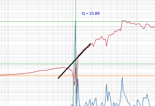
I am not familiar with the graph format used by your instrument, (I generally work with s parameters and derived quantities) but I imagine that the Q is for example defined by the ratio of the equivalent parallel damping resistance to the reactance, or the inverse of the tanδ.
Based on the magnitude curve, what happens at ~1.5MHz looks very much like the series resonance of a capacitor, except it is more complex, and has a middle peak where the impedance briefly becomes reactive again, if my interpretation is correct.
This peak would be problematic if it exceeded the linear interpolation between, say ~800kHz and 2 MHz, but it doesn't:

Simple series resonances alone are not problematic: they don't impair the ability of the supply to present a low impedance to the external world, they just improve this ability for one particular frequency.
When the resonances are more complex, as with multiple paralleled caps for example, they can result in a parallel resonance which greatly increases the impedance at one or more frequencies, which is detrimental, but here the complex behavior seems limited enough to be innocuous.
If possible, it would be interesting to increase the resolution (number of points) of the analysis, to be sure that a much higher peak is not lost between two points.
To summarize: based on what I see and the interpretation I make, the behavior does not look problematic: to the load, the only relevant parameter is the magnitude of the supply's impedance (one could find exceptions for pathological loads, but very peculiar sets of conditions would be required to make it happen at the right frequency)
What I cannot explain is why this resonance appears at such a low frequency, for such a small resistance change.
Based on the magnitude curve, what happens at ~1.5MHz looks very much like the series resonance of a capacitor, except it is more complex, and has a middle peak where the impedance briefly becomes reactive again, if my interpretation is correct.
This peak would be problematic if it exceeded the linear interpolation between, say ~800kHz and 2 MHz, but it doesn't:
Simple series resonances alone are not problematic: they don't impair the ability of the supply to present a low impedance to the external world, they just improve this ability for one particular frequency.
When the resonances are more complex, as with multiple paralleled caps for example, they can result in a parallel resonance which greatly increases the impedance at one or more frequencies, which is detrimental, but here the complex behavior seems limited enough to be innocuous.
If possible, it would be interesting to increase the resolution (number of points) of the analysis, to be sure that a much higher peak is not lost between two points.
To summarize: based on what I see and the interpretation I make, the behavior does not look problematic: to the load, the only relevant parameter is the magnitude of the supply's impedance (one could find exceptions for pathological loads, but very peculiar sets of conditions would be required to make it happen at the right frequency)
What I cannot explain is why this resonance appears at such a low frequency, for such a small resistance change.
Attachments
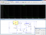
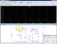
Building that on solderless board is brave and bold; managing to make it work is heroic!
I built the first proto of the denoiser on breadboard, but I didn't even attempt it for the nonoiser: I went directly for the perfboard, and before soldering anything I carefully planned the layout.
Even so, I managed to get the Kelvin connections slightly wrong
I built the first proto of the denoiser on breadboard, but I didn't even attempt it for the nonoiser: I went directly for the perfboard, and before soldering anything I carefully planned the layout.
Even so, I managed to get the Kelvin connections slightly wrong
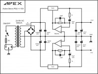
At first glance the D-Noizator seems to be similar in principle to apexaudio's active power supply. If this is the case then is there any advantage/disadvantage to be gained by using an opamp rather than a transistor as the active element? The D-Noizator obviously has an enormous advantage costwise. Does anyone know if apexaudio was the originator of the opamp noise reducer circuit or if it goes back further than that? It is certainly appears frequently in products from China on ebay, but I sincerely doubt that this is the original source of the opamp circuit.
Attachments
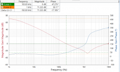
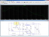
Let me get in there and break the loop to the ADJ pin on the LM317 for a more conventional bode plot.
I had built discrete equivalent LM317 in a simulation.
The equivalent circuit diagram and R, C values are taken from this website.
"https://www.zawa2.com/ZZsim/integ_lm317.html"
Attachments
If you don't make use of the opamp's DC accuracy, as in the Apex circuit, the transistor circuit clearly has an edge: a humble BC337 and even a cheapo S8050 outperforms most of the "low-noise" opamps, except the very best ones (and most expensive) like the AD797.At first glance the D-Noizator seems to be similar in principle to apexaudio's active power supply. If this is the case then is there any advantage/disadvantage to be gained by using an opamp rather than a transistor as the active element?
If you use a ZTX851 or similar (which is not that expensive), there is no competition anymore.
In addition, a simple transistor has less phaseshift than an opamp, which is an advantage for loop stability
I think I have hazy reminiscences of app notes from NS using an opamp to sublimate a regular 3-pin reg into a high perf one, but I could be wrong, and the manufacturer could also be another one....Does anyone know if apexaudio was the originator of the opamp noise reducer circuit or if it goes back further than that? It is certainly appears frequently in products from China on ebay, but I sincerely doubt that this is the original source of the opamp circuit.
But the opamp + reg combo definitely rings a bell
I had built discrete equivalent LM317 in a simulation.
The equivalent circuit diagram and R, C values are taken from this website.
"https://www.zawa2.com/ZZsim/integ_lm317.html"
That could be interesting.
Note that due to the configuration of the 317 (ref tied to the output node), you cannot break the loop in a conventional manner if you want to include the 317's gain in the loop.
Here is an example of rearranged configuration allowing the full loop inclusion without an access to internal nodes:
Of course, if the transistor-level model is really accurate, it may be simpler to break the loop in a more convenient way
PS:
Based on the sim above, the circuit should oscillate at ~10MHz, but in real life it doesn't: unlike its model, the real 317 becomes completely dead above ~5MHz: it just becomes a lump of plastic and metal, and you could even remove the power without greatly affecting its characteristics
Attachments
Last edited:
- Home
- Amplifiers
- Power Supplies
- D-Noizator: a magic active noise canceller to retrofit & upgrade any 317-based V.Reg.