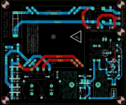
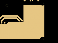
Yet another PCB layout of the De-Noiser. This one uses a four layer board (!!) and includes a jumper option to disable/enable the De-Noiser. Gerber files freely downloadable.
VRDN: bipolar regulator PCB for line level ckts: ±11V to ±20V @ 1.5A with "De-Noiser"
VRDN: bipolar regulator PCB for line level ckts: ±11V to ±20V @ 1.5A with "De-Noiser"
Yet another PCB layout of the De-Noiser. This one uses a four layer board (!!) and includes a jumper option to disable/enable the De-Noiser. Gerber files freely downloadable.
VRDN: bipolar regulator PCB for line level ckts: ±11V to ±20V @ 1.5A with "De-Noiser"
Things seem to be going the opposite way for this project: getting expensive.
For that money I would invest on a Jung Superregulator which has been proven much better audio wise.
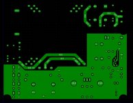
Ya think ya got enough capacitors on that thang??Yet another PCB layout of the De-Noiser.
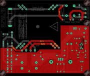
Here is my final solution. Comments about the board noted and addressed.
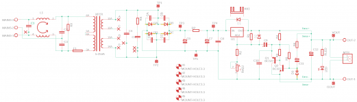
Secondaries can be customised for parallel (A+B, C+D) or series (B+C). I've experimented with custom primary jumpers, but it looks rather messy, so this is 230V for now. Would be responsive if people are really desperate for 110V.

Has been really fun and an enjoyable learning experience. Thanks Nisbeth for letting me loose on it")
Gerbers attached, UNTESTED, but verified error-free in Eagle.
For some reason, the polygon pads look filled on the copper layers in most free online Gerber viewers but are correctly isolated on PCBway? Not sure why. Going to take this to fabrication in a couple of days.
Secondaries can be customised for parallel (A+B, C+D) or series (B+C). I've experimented with custom primary jumpers, but it looks rather messy, so this is 230V for now. Would be responsive if people are really desperate for 110V.
Has been really fun and an enjoyable learning experience. Thanks Nisbeth for letting me loose on it
Gerbers attached, UNTESTED, but verified error-free in Eagle.
For some reason, the polygon pads look filled on the copper layers in most free online Gerber viewers but are correctly isolated on PCBway? Not sure why. Going to take this to fabrication in a couple of days.
Attachments
Last edited:
For some reason, the polygon pads look filled on the copper layers in most free online Gerber viewers but are correctly isolated on PCBway? Not sure why. Going to take this to fabrication in a couple of days.
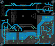
Here is what I meant.
Attachments

Looks very good.
May I ask why will you order from PCBWay?
I’ve recently switched to JLCPCB. Your design is 40$ at PCBWay and 7$ at JLCPCB. I’ve ordered mine from JLCPCB and quality is excellent. Both ship with DHL Express at same price.
I'll probably use JLC. I bought your board from there, awaiting shipping.
Just wanted to check the Gerbers through different places. Only PCB Way showed the isolated pads.
Otherwise JLC, pcbxprt.com, gerber-viewer.com - they all showed filled pads on the copper layer. Not really sure why.
I did check wih KiCad gerber viewer and it shows as OK. There are some warnings of unexpected characters on job file, but that could be some difference between Eagle and KiCad.
If you don’t use latest Eagle version, it could be good to upgrade (if possible) and check again.
If you don’t use latest Eagle version, it could be good to upgrade (if possible) and check again.
Attachments
Thanks for your contribution to the community.Yet another PCB layout of the De-Noiser. This one uses a four layer board (!!) and includes a jumper option to disable/enable the De-Noiser. Gerber files freely downloadable.
VRDN: bipolar regulator PCB for line level ckts: ±11V to ±20V @ 1.5A with "De-Noiser"
Your version is "maximalized", as noted by other members, but that is globally the trend followed since the thread was started.
Initially, what I had in mind when designing the project was a tiny (probably SMD) 3-wire add-on module that could convert any "normal" 317 regulator into a superreg (kind of), cheaply and easily.
Things turned out differently, and although I am pretty sure that a number of members did actually follow the initial scope without telling anyone, most of the projects posted so far are complete, superreg-like regulators.
I do not have any objection to that, and once a project is posted, it gets a life of its own and its creator doesn't control it any more.
I am certain that the convenience you added by providing a PCB, BOM and other essential aspects will please many members whilst irritating others, but there is room enough for everyone: basically, do as you like and follow your own path.
Since you have started your dedicated thread, the "purists" here won't be inconvenienced by it (but personally, I don't mind).
Yep. The emphasis of VRDN is high current and high integration, plus "AC wall wart if you prefer"; while De-Noiser is merely one of its features. However I suspect DN might turn out to be the deciding factor which draws in the most DIY builders. A hard-to-resist Sales Feature.
This a builder's place, so it's far from me to criticize how my pals here prefer to build their stuff.
When I commented on how things were diverting from what I thought was the original intention, improving an existing regulator, it was just to point it out.
I keep working in that direction. In fact I will be soon uploading another "prototype board", this time from Diego's Dienoiser.
I will also upload another version of the Denoisator, which had some mistakes in it.
This a builder's place, so it's far from me to criticize how my pals here prefer to build their stuff.
When I commented on how things were diverting from what I thought was the original intention, improving an existing regulator, it was just to point it out.
I keep working in that direction. In fact I will be soon uploading another "prototype board", this time from Diego's Dienoiser.
I will also upload another version of the Denoisator, which had some mistakes in it.
Thx for your effort and yes I think it is quite fun and learning from this as my great interest in electronics and hifi😊
Here are the values that simulation predicts to be good for the 3,3V output. It is roughly the same for 5V, except R2 value.
Have you or other ordered pcb for this version?
Initially, what I had in mind when designing the project was a tiny (probably SMD) 3-wire add-on module that could convert any "normal" 317 regulator into a superreg (kind of), cheaply and easily.
I guess this layout is more according to Elvee's original vision
Electrolytics are Nichicon low-profile (100u/35V and 22u/35V).
It is a dienoiser with denoiser stuff in the bottom and dienoiser add-ons on top. However dienoiser seems to be very prone to oscillations and I could not measure any real improvements agains denoiser in practice. So I will probably only use it as a denoiser.
Attachments
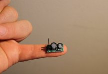
YESSS!!! ExactlyI guess this layout is more according to Elvee's original vision
Very cleverIt is a dienoiser with denoiser stuff in the bottom and dienoiser add-ons on top.
That's strange: I didn't use the dienoiser in reality, but I tested it on a breadboard (which is normally more demanding), and apart from requiring a larger compensation cap, it looked perfectly stableHowever dienoiser seems to be very prone to oscillations and I could not measure any real improvements agains denoiser in practice. So I will probably only use it as a denoiser.
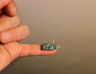
Have you or other ordered pcb for this version?
Do you refer to single rail dienoiser version? If so, details can be found in the posts 753, 764 (gerbers) and 811. I’m waiting for some parts and will confirm till Thursday if design is in order.
I guess this layout is more according to Elvee's original vision
Electrolytics are Nichicon low-profile (100u/35V and 22u/35V).
It is a dienoiser with denoiser stuff in the bottom and dienoiser add-ons on top. However dienoiser seems to be very prone to oscillations and I could not measure any real improvements agains denoiser in practice. So I will probably only use it as a denoiser.
That's so lovely! Amazing work of miniturisation
About the oscillation from the Sziklai Pair: Presumably you used a decent C4 value and reasonable ESR in/out caps?
I guess this layout is more according to Elvee's original vision
Electrolytics are Nichicon low-profile (100u/35V and 22u/35V).
It is a dienoiser with denoiser stuff in the bottom and dienoiser add-ons on top. However dienoiser seems to be very prone to oscillations and I could not measure any real improvements agains denoiser in practice. So I will probably only use it as a denoiser.
Dayum!
WOW!! Great effort! That looks really small! How about posting the gerber files and a B.O.M.?I guess this layout is more according to Elvee's original vision
Electrolytics are Nichicon low-profile (100u/35V and 22u/35V).
It is a dienoiser with denoiser stuff in the bottom and dienoiser add-ons on top.
- Home
- Amplifiers
- Power Supplies
- D-Noizator: a magic active noise canceller to retrofit & upgrade any 317-based V.Reg.