I just made the ultimate, most reliable sim possible: a breadboard test.
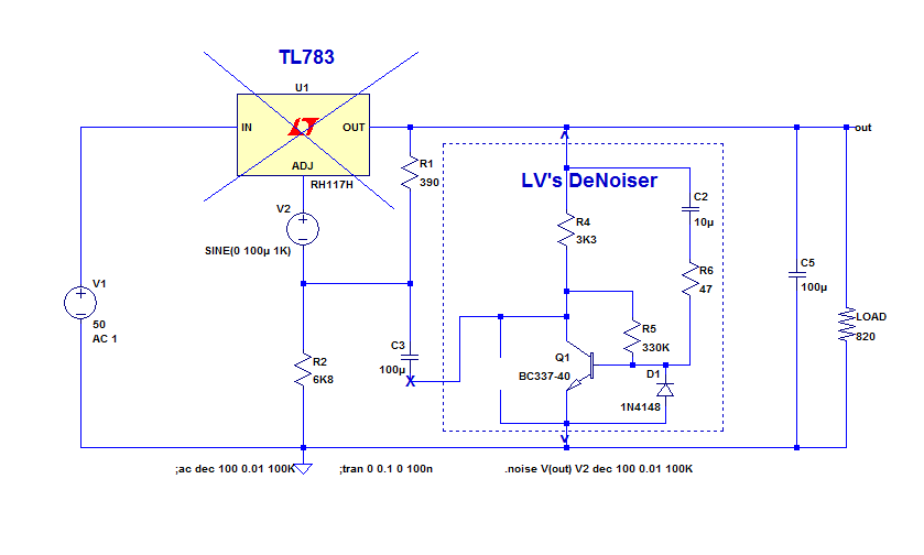
I have somewhat adapted the values to reduce the dissipation, but that's still a denoiser:
Result?
It works, and it is even more tolerant than a regular 317: it is stable without the 10nF compensation cap, however I don't recommend omitting it: it could be on the verge of oscillation.
It should work equally well with a nonoiser or a Dienoiser, since it looks so easy to live
Attachments

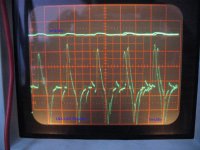
I made a quick test how good could be d-noiser used for heating tubes and it's not bad at all. I didn't measured ripple with HP334A like last time cause that part of workbench is a mess,but i used oscilloscope at 5mV/div and tube was EL84 6,3V/760mA, cables from PSU to tube we're around 50cm long so i soldered 220nF cap on tube socket.
D-noiser gave me around 1mV ripple and i coudn't see any sign of 100Hz from rectifier, only some higher frequency ripple that with very low amplitude.
Classic lm317 with cap on ajd pin gave me 5mV good old 100Hz ripple that contained a lot of higher frequency noise.
In most cases i don't think there is need for such a clean voltage for heater but for MM phono preamps and maybe if somebody is crazy enough to build MC preamp with tubes this could be nice and cheap PSU.
Good to know, but slightly disappointing at the same time: the improvement with the denoiser should be in the region of ~30dB, unless there is a source of really high frequency noise somewhere (in the regulator or the measurement loop)D-noiser gave me around 1mV ripple and i coudn't see any sign of 100Hz from rectifier, only some higher frequency ripple that with very low amplitude.
Classic lm317 with cap on ajd pin gave me 5mV good old 100Hz ripple that contained a lot of higher frequency noise.
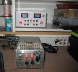
I made a test today with my simple LNA. With x100 LNA i could measure 50uV/div. I made mini lab supply with denoiser so there is chinese AVmeter connected to it all the time. Supply voltage for AVmeter is taken from bulk elcos just after rectifier so denoiser and AVmeter share same supply.
After measurement i made other day(without LNA) i decided i'll use denoiser for my next tube project(one denoiser will supply heater voltage for two ECC88) so in couple of days i'll test denoiser as it is without any modifications and post results,until then this is my test with EL84.
Upper line is simple x1 probe,down is with LNA x100.
P.S.
Ignore my really old supply in plain box on table. Denoiser supply is one that is pretty with chinese AVmeters.
Attachments
Yeah, typical crap generated by multiplexing, but even with a common supply source, it should be possible to eliminate it almost completely.I made a test today with my simple LNA. With x100 LNA i could measure 50uV/div. I made mini lab supply with denoiser so there is chinese AVmeter connected to it all the time. Supply voltage for AVmeter is taken from bulk elcos just after rectifier so denoiser and AVmeter share same supply.
Did you properly twist the supply cables (separetely, of course)?
Didn't you make inadvertently a ground loop somewhere?
I don't think i have a ground loop. Denoiser "lab supply" is not grounded/earthed. LNA battery supply ground is connected through BNC input. So only thing i have earthed is oscilloscope.
Cables from psu to el84 we're twisted and since i have two individual denoisers in my psu they have cables twisted separetely.
Cables from psu to el84 we're twisted and since i have two individual denoisers in my psu they have cables twisted separetely.
So, I am refurbishing my old mixing console; I definitely am putting Elvee's de-noiser on the existing LM317/337-based power supply. Also replacing the power supply bypass caps on each of the modules, as they are 35+ years old. The question is, with my now 30-db-noise-reduced power source, is there any advantage to using the very expensive Elna SILMIC caps to replace the existing electrolytic bypassers? Or will simple Panasonic FCs do just as well?
Hi @Khadgar2007 - nice power supply in your picture. Quick question about the chinese AV meters. I have the same ones (and some similar V only meters) that I was thinking of using. Did you notice or measure if they introduce any additional noise or grunge when fitted? I've seen the odd comments on other threads and forums about extra noise after fitting, so I don't want to add noise back into the Denoiser.... Thanks Adrian
That's big question. I didn't measure noise i get from those AV meters.I have measured denoiser(stand alone without AV meter) that is in my PSU some time ago and i know noise it has on it's own. So i could measure noise now and compare it.
But from this project i didn't expected to get best performances but just some better then basic lm317 bench supply.
But from this project i didn't expected to get best performances but just some better then basic lm317 bench supply.
I have the same, and as any similar gear, they are quite noisy which is normal for something having a multiplexed display, and perfectly manageable if you follow good wiring practices.
The supply wires must be twisted and go directly to the source: the module has to be completely independent from the rest.
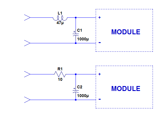
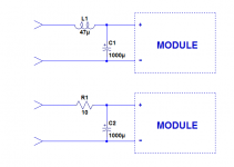
A good supply bypass is essential: either you connect directly to the reservoir cap, or you use a substantial bypass cap directly on the module: 1000µF for example.
You can also a RC or LC filter in the supply (near the module):
You also need to avoid ground loops: you have to think about the way of connecting the input ground without creating one.
Finally, the module should not be too close to the denoiser to avoid electrostatic coupling.
The denoiser is mostly low impedance, but at a close distance the 0/5V transitions will couple into the output of the correction amplifier
The supply wires must be twisted and go directly to the source: the module has to be completely independent from the rest.
A good supply bypass is essential: either you connect directly to the reservoir cap, or you use a substantial bypass cap directly on the module: 1000µF for example.
You can also a RC or LC filter in the supply (near the module):
You also need to avoid ground loops: you have to think about the way of connecting the input ground without creating one.
Finally, the module should not be too close to the denoiser to avoid electrostatic coupling.
The denoiser is mostly low impedance, but at a close distance the 0/5V transitions will couple into the output of the correction amplifier
Attachments
- yes they add some noise if powered from the same power supply.Quick question about the chinese AV meters. I have the same ones (and some similar V only meters) that I was thinking of using. Did you notice or measure if they introduce any additional noise or grunge when fitted?
I see now that Elvee said how to minimize it.
Your Panasonic are perfectly fine. Using Silmic at the output could even cause problems (also with an unmodified 317)The question is, with my now 30-db-noise-reduced power source, is there any advantage to using the very expensive Elna SILMIC caps to replace the existing electrolytic bypassers? Or will simple Panasonic FCs do just as well?
THANKS for your work in making this available! I just ordered 10 boards from JLCPCB. Looking forward to see how this works out!!I have made a dual rail pcb that works as intended.
Attached are the gerber files that can be used to order pcbs from a PCB fab such as www.jlcpcb.com
As long as the filtering is sufficient to keep the regulators in their dropout comfort zone, no.
If a trough of the input ripple breaks into the 2~3V dropout zone, you evidently need to do something, but using a higher input voltage would be the sensible solution, increasing the caps would be the last resort option.
If a trough of the input ripple breaks into the 2~3V dropout zone, you evidently need to do something, but using a higher input voltage would be the sensible solution, increasing the caps would be the last resort option.
If you add a series resistor before the input cap, like 1R, the improvement would be much better than increasing the input capacitor.
PSRR @ 10KHz goes down 43dB, from -95dB to -138dB using just 2200uF.
Without the resistor, and replacing the cap with 10000uF, PSRR remains the same at 10KHz: -95dB. If you add the 1 ohm series resistor with that cap, PSRR goes even lower: -151dB. But I don't think the additional cost or larger cap diameter would justify the PSRR improvement.
Even an RC with 1 ohm and 1000uF, with a modest -131dB improvement at 10KHz is a better option. The curve stays below -126dB up to 100KHz. A remarkable thing.
- Home
- Amplifiers
- Power Supplies
- D-Noizator: a magic active noise canceller to retrofit & upgrade any 317-based V.Reg.