The quality of C1 (or C2 for that matter) doesn't matter the least: they are both degenerated with a substantial explicit or implicit series resistance, meaning you can use any crap you have, even a half-dried one would still work OKSince C1 position senses noise and related audio modulation, is there a need to install a very good quality cap here? Has anyone experimented to check on capacitor changes and impact on sound quality?
Ravi
What VAC on the secondary (loaded)? What is the resistance of the secondary winding?
Secondary is 14VAC and I have about 18.5VDC after rectification. Two RCRC filters and would like to use LM317 Denoiser for tube heating. Can LM317 withstand that permanently? Or maybe LM338?
Regards
I never tested ZTX's on the dienoiser, thus you have to rely on Trileru's tests@Elvee Any recommendations on using the ZTX transistors with the dienoiser? I have tried numerous combinations and they all seem to be good, then deteriorate and become unstable with time or are unstable from the start.
Secondary is 14VAC and I have about 18.5VDC after rectification. Two RCRC filters and would like to use LM317 Denoiser for tube heating. Can LM317 withstand that permanently? Or maybe LM338?
Regards
LM317 is rated for 1.5A max output. As long as you have adequate cooling I don't think 1.2A sustained is going to be an issues.
I did post measurements for around 11.3Vout at 1.25A.
If you want to also use the capacitance multiplier (I recommend the version with Sziklai pair) you could use the rev1.5 pcb.
I attached the sim file. You'd have to use Schottky diodes for rectification. I estimated your secondary resistance, you should probably measure it to make sure.
You'd also have to use a 3900uF/25V cap after rectification. That cap has to have a ac current rating higher than 2Arms. A good candidate that would fit on the rev1.5 pcb is EKYB250ELL392ML25S from Nippon Chemi-Con, has 3.14A ripple current rating. Or anything that is 16mm diameter with higher than 2A ripple current rating.
With the configuration in the sim file you'd have a PSRR of around 185dB at 100Hz, for 12.6Vout / 1.2Aout.
LT108x have higher PSRR but a bit harder to keep stable.
edit: the cm transistor and LM317 would dissipate around 2.5-3W each with the configuration in the sim file.
Attachments
Last edited:
And let's remind ourselves that 20-bit digital audio has a best case signal to noise ratio of 120dB, while 24-bit digital audio has a best case signal to noise ratio of 145dB. Vinyl playback is considerably less 
These numbers might help DIYers estimate "what target is good enough?"
Recall that Line_regulation_at_the_analog_output = (Line regulation of power supply) x (PSRR of the analog circuitry).
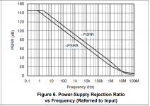
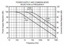
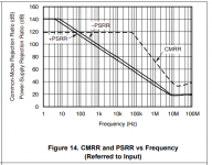
Here are some representative plots of (PSRR of the analog circuitry). Part number embedded in the filename, hover your mouse to read it.
_
These numbers might help DIYers estimate "what target is good enough?"
Recall that Line_regulation_at_the_analog_output = (Line regulation of power supply) x (PSRR of the analog circuitry).
Here are some representative plots of (PSRR of the analog circuitry). Part number embedded in the filename, hover your mouse to read it.
_
Attachments
Last edited:
There's many applications for a low noise supply where opamps aren't involved (discrete preamps). Opamps do have PSRR but at the same time previous stages also benefit from the clean DC.
Also the increased PSRR helps with less filter capacitance after the bridge. Might come out cheaper. If 180-190dB of PSRR is not so hard to obtain and with little (relatively) input capacitance, why not?
Also the increased PSRR helps with less filter capacitance after the bridge. Might come out cheaper. If 180-190dB of PSRR is not so hard to obtain and with little (relatively) input capacitance, why not?
The quality of C1 (or C2 for that matter) doesn't matter the least: they are both degenerated with a substantial explicit or implicit series resistance, meaning you can use any crap you have, even a half-dried one would still work OK
Thanks for the clarification Elvee
@Mark Johnson - agreed, pretty much anything under-140 is probably overkill. I'm actually trying to get the lowest noise out of my LNA is why I am wanting to use the ZTX transistors. And let's face it, if 240hp is good in a GTI, 400hp has to be better! Yea, I'm the guy who wanted to put a 455 Buick engine in a Chevette.
Would you say the capacitance multiplier is wasteful of pcb space? I wouldn't gain much by removing it. But without in the case of LM317+dieoniser the total PSRR would come under 140dB, at 125dB or so.
So do you think it's an issue that together they offer too much PSRR performance?
So do you think it's an issue that together they offer too much PSRR performance?
LM317 is rated for 1.5A max output. As long as you have adequate cooling I don't think 1.2A sustained is going to be an issues.
I did post measurements for around 11.3Vout at 1.25A.
If you want to also use the capacitance multiplier (I recommend the version with Sziklai pair) you could use the rev1.5 pcb.
I attached the sim file. You'd have to use Schottky diodes for rectification. I estimated your secondary resistance, you should probably measure it to make sure.
You'd also have to use a 3900uF/25V cap after rectification. That cap has to have a ac current rating higher than 2Arms. A good candidate that would fit on the rev1.5 pcb is EKYB250ELL392ML25S from Nippon Chemi-Con, has 3.14A ripple current rating. Or anything that is 16mm diameter with higher than 2A ripple current rating.
With the configuration in the sim file you'd have a PSRR of around 185dB at 100Hz, for 12.6Vout / 1.2Aout.
LT108x have higher PSRR but a bit harder to keep stable.
edit: the cm transistor and LM317 would dissipate around 2.5-3W each with the configuration in the sim file.
Can you share LM317 file with me, please? I am having trouble with importing a model to LTSpice. I imported one LM317, but with it, I have 8.2Vout with this simulation file and that is wrong. LM338 can be used in place of LM317, yes?
Regards
You can get the model from here: https://www.ti.com/product/LM317-N#design-development##design-tools-simulation
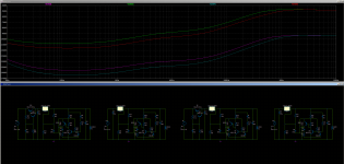
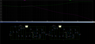
Here's the performance for 3.3Vout and 5Vout. I used the LM317N for the simulation, the normal LM317 has a 5dB or so performance hit.
As you can see at 3.3V it barely goes over 100dB for PSRR. So then you can see how it's useful to also have the capacitance multiplier available for that extra 50dB or so of PSRR.
You can also just bypass it on the pcb by shorting the C-E of the cap multi pass transistor.
edit:
I added another photo showing the difference with adding a LC filter in front of the cap multi. For 3.3Vout for digital I'd say it's adequate. Using a regular LM317 you can shave about 5dB of PSRR. So about 150dB total at 100Hz doesn't seem like an exaggeration.
My smd boards have the LC footprints as well.
Attachments
Last edited:
- Home
- Amplifiers
- Power Supplies
- D-Noizator: a magic active noise canceller to retrofit & upgrade any 317-based V.Reg.