I made a comparison with a simple dienoiser with LM317, measuring CMRR and just changing the input filter.
C, R + C, and CM.
The last two curves seem pretty good to me, so I would go with the R + C.
The only important difference is the slightly higher drop after the input resistor, which was 6V vs 4V on CM.
But I can live with that for that low current supply.
That should be the one I plan to compare with the SuperRegulator on the RIAA preamps. And listen to them.
Attachments

Last edited:
Or just drop in another LM317 in the upstream position, and get improved PSRR all the way down to DC. Its drop is 3.5 volts which is lower than 4V and also lower than 6V.
I made a comparison with a simple dienoiser with LM317, measuring CMRR and just changing the input filter.
C, R + C, and CM.
The last two curves seem pretty good to me, so I would go with the R + C.
The only important difference is the slightly higher drop after the input resistor, which was 6V vs 4V on CM.
But I can live with that for that low current supply.
That should be the one I plan to compare with the SuperRegulator on the RIAA preamps. And listen to them.
I think the kind of capacitance multiplier you use matters in this case.
The ones I have on my boards (either Darlington pair either Sziklai pair) would offer around 56dB (at 100Hz) for your simulation conditions.
The Darlington pair has a Vdrop of around 1.42V and would dissipate 0.19W and the Sziklai pair has a Vdrop of around 0.9V and would dissipate around 0.12W.
The RC resistor offers about 30dB PSRR (at 100Hz), has a Vdrop of around 6.6V and dissipates 0.92W.
Also for that output voltage I suggest you change R4 to 3.3k, R5 to 330k, R3 to 560R. Maybe even lower R6 to 33R.
R15 in my schematic should be 560K for best performance at 1A.
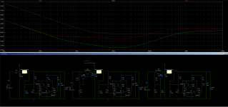
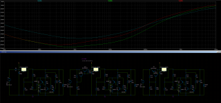
First picture is the PSRR for just the RC/cap multi outputs, and the second picture is the output of the regulator for each case.
edit: if you want the least Vdrop then the Sziklai pair capacitance multiplier seems like the best choice. It has lower Vdrop (0.9V in your case) than a LM317 and about the same PSRR (at 100Hz) as a simple LM317 configuration.
The RC values would also have to change if you increase the output current from 100mA to 1-1.5A.
Say for 1A output for the same circuit, no change to the capacitance multiplier, it still offers the 56dB PSRR at 100Hz, just that now the Darlington pair drops 1.75V and dissipates 1.8W, the Sziklai pair version drops 1.1V and dissipates 1.1W.
To keep the min voltage across the regulator we need to dial down the value for the RC resistor to around 6.8R, it drops almost 7V and dissipates 7W of heat. And in total it offers just 13dB PSRR at 100Hz.
So no change to the capacitance multiplier, maybe a small heatsink on the pass transistor.
Attachments
Last edited:
Or just drop in another LM317 in the upstream position, and get improved PSRR all the way down to DC. Its drop is 3.5 volts which is lower than 4V and also lower than 6V.
On the +/-30v regulator using two 317 would be difficult because the input levels would be critical if there's an eventual drop from AC line, particularly on the first LM317. A CM or Sziklai pair would be better. I do insist on having +/-40v as input raw DC voltage on this project.
Trileru, I just did not understand the high CMRR numbers for your three curves, compared to mine.
Something against CM or Sziklai are that they demand a heatsink, which I would also need on the 317. But current demands of the RIAA preamp is about 15mA on each side, so maybe single aluminum plate for transistors and regulators would do.
Last edited:
They require a heatsink past 500mA or so. They don't need one for 100mA output.
What don't you understand from the graphs I posted compared to yours?
What don't you understand from the graphs I posted compared to yours?
They require a heatsink past 500mA or so. They don't need one for 100mA output.
What don't you understand from the graphs I posted compared to yours?
The dB figures on the left, supposedly showing how low they can get in CMRR. Yours go down to 84dB, mine to 190dB.
Last edited:
The dB figures on the left, supposedly showing how low they can get in CMRR. Yours go down to 84dB, mine to 190dB.
I mentioned the photo on the left shows only the capacitance multipliers/RC filter performance. The LM317+dienoiser performance is identical for all three versions so it's simpler to look at the difference between the two cap multi and RC filter only.
I mentioned the specs on the right, because I remember Elvee mentioning that anything below -100dB on CMRR was more than enough and probably inaudible.
As you might remember, I intend to use 3X7 kits for the projects, with or without ground plane. Adding the RC resistor on the board is relatively easy, and that's why I would sacrifice better specs that might not make an audible change to use these boards.
Later on I would have to design several pcbs, so I would then clone the one you did, which is certainly better.
Big sorry, my mistake. I mean the dB specs on the left, not on the right.
You must be thinking what I'm talking about.
You must be thinking what I'm talking about.
NoNoiser- C1 choice relevant?
Just installed the NoNoiser regulator in my Nakamichi 582 as an upgrade of usual 78/7912 regulators. Big Thanks Elvee for the great design and Jack for sharing the PCB gerbers that were used to fabricate the PCBs. Using remote sensing to wire using a single core co-ax. The voltages are reasinably stable, with the -ve regulator DC level showing a bit more wander around set level (12v).
When I was upgrading many old capacitors in the deck, I found that the coupling cap to headphone output improved when I added Silmic caps to std Panasonic caps of 100mfd value.
Since C1 position senses noise and related audio modulation, is there a need to install a very good quality cap here? Has anyone experimented to check on capacitor changes and impact on sound quality?
Ravi
Do you have ASC file for LM317, please? It will be used for tube heating, 12.6V 1.2A.
Regards
Regards
Just installed the NoNoiser regulator in my Nakamichi 582 as an upgrade of usual 78/7912 regulators. Big Thanks Elvee for the great design and Jack for sharing the PCB gerbers that were used to fabricate the PCBs. Using remote sensing to wire using a single core co-ax. The voltages are reasinably stable, with the -ve regulator DC level showing a bit more wander around set level (12v).
When I was upgrading many old capacitors in the deck, I found that the coupling cap to headphone output improved when I added Silmic caps to std Panasonic caps of 100mfd value.
Since C1 position senses noise and related audio modulation, is there a need to install a very good quality cap here? Has anyone experimented to check on capacitor changes and impact on sound quality?
Ravi
As I don't have the 582 there's not much I can suggest, but some I will:
1) Do you know what Nakamichi used as active parts for outputs, line and headphone?
2) Can you measure the DC offset on each one?
3) If it's using ICs, which are they? Most likely 5532 or similar. If you know how to do it, you could extract the ICs and put quality 8 pin socket. Then try more modern ICs that will allow you to bypass the output capacitors.
4) I do not undesrtand what noise C1 might be sensing or what it does?
5) Did you notice changes after adding the Nonoiser? What were they?
Also for that output voltage I suggest you change R4 to 3.3k, R5 to 330k, R3 to 560R. Maybe even lower R6 to 33R.
R15 in my schematic should be 560K for best performance at 1A.
What about the series resistor with C4 should stay or go? Perhaps leave the space to use it bypassed and see if it's necessary.
I think the kind of capacitance multiplier you use matters in this case.
The ones I have on my boards (either Darlington pair either Sziklai pair) would offer around 56dB (at 100Hz) for your simulation conditions.
The Darlington pair has a Vdrop of around 1.42V and would dissipate 0.19W and the Sziklai pair has a Vdrop of around 0.9V and would dissipate around 0.12W.
The RC resistor offers about 30dB PSRR (at 100Hz), has a Vdrop of around 6.6V and dissipates 0.92W.
Also for that output voltage I suggest you change R4 to 3.3k, R5 to 330k, R3 to 560R. Maybe even lower R6 to 33R.
R15 in my schematic should be 560K for best performance at 1A.
First picture is the PSRR for just the RC/cap multi outputs, and the second picture is the output of the regulator for each case.
edit: if you want the least Vdrop then the Sziklai pair capacitance multiplier seems like the best choice. It has lower Vdrop (0.9V in your case) than a LM317 and about the same PSRR (at 100Hz) as a simple LM317 configuration.
The RC values would also have to change if you increase the output current from 100mA to 1-1.5A.
Say for 1A output for the same circuit, no change to the capacitance multiplier, it still offers the 56dB PSRR at 100Hz, just that now the Darlington pair drops 1.75V and dissipates 1.8W, the Sziklai pair version drops 1.1V and dissipates 1.1W.
To keep the min voltage across the regulator we need to dial down the value for the RC resistor to around 6.8R, it drops almost 7V and dissipates 7W of heat. And in total it offers just 13dB PSRR at 100Hz.
So no change to the capacitance multiplier, maybe a small heatsink on the pass transistor.
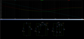
The only difference between both circuits and curves on the left are right is the current you are running on them?
Do you have ASC file for LM317, please? It will be used for tube heating, 12.6V 1.2A.
Regards
What VAC on the secondary (loaded)? What is the resistance of the secondary winding?
What about the series resistor with C4 should stay or go? Perhaps leave the space to use it bypassed and see if it's necessary.
C4 should be between 22nF and 47nF, and I also recommend adding 1R to 3.9R on any implementation for dienioser. With the output capacitors I recommend usually dienoiser works with around 47nF+3.9R.
The only difference between both circuits and curves on the left are right is the current you are running on them?
There's three circuits in that photo.
The left most one uses a RC filter on the input, the middle one a Darlington pair capacitance multiplier, and the one on the right uses a Sziklai pair capacitance multiplier. Same input/output voltages for all, same current.
I made another sim with just the RC filter and capacitance multiplier versions so it's less confusing. Each one's PSRR is added to the one from the LM3x7+dienoiser when you measure the PSRR on the output of LM3x7.
Attachments
- Home
- Amplifiers
- Power Supplies
- D-Noizator: a magic active noise canceller to retrofit & upgrade any 317-based VReg