I'm using a Focusrite Solo 3rd gen. with a +60dB Low noise Amplifier (LNA). The software is ARTA.
Sorry for my ignorance but I didn't get the +60dB extra gain here. Graphs already at -140dB so, is actual circuit is around -200dB (which is not possible in regular environment)? Or your graphs adjusted for extra +60dB in software? In this case real ARTA measurements should be at around -80dB which in specs of Scarlet 3rd gen, right?
The dynamic range on that audio card is 110dB on instrument input.
The 60dB from the LNA don't count towards these 110dB of range. As long as the resulting signal from the LNA is inside this 110dB window it should be fine.
I presume his measurements include the 60dB. I should also update ARTA to include the gain of the LNA.
The 60dB from the LNA don't count towards these 110dB of range. As long as the resulting signal from the LNA is inside this 110dB window it should be fine.
I presume his measurements include the 60dB. I should also update ARTA to include the gain of the LNA.
I should also update ARTA to include the gain of the LNA.
And please make your graph legends are readable. Your graph legends look like photo negatives.
That is an unfortunate side effect of me overlaying screenshots in GIMP. I use the "Exclusion" filter or what that is so the area of interest looks good. Sorry about that, but it's the fastest way I found to overlay screenshots.
I presume his measurements include the 60dB.
So, -140dB real world performance is guaranteed with bare denoiser? I think that this number, even -120dB is an exceptional real world performance.
That is an unfortunate side effect of me overlaying screenshots in GIMP. I use the "Exclusion" filter or what that is so the area of interest looks good. Sorry about that, but it's the fastest way I found to overlay screenshots.
Do you have, maybe, a simulation with Vout 19 - 20V 3A? It is good to replace an AC adapter for laptop or small computer for audio source.
Regards
So, -140dB real world performance is guaranteed with bare denoiser? I think that this number, even -120dB is an exceptional real world performance.
Don't mistake PSRR with noisefloor.
Do you have, maybe, a simulation with Vout 19 - 20V 3A? It is good to replace an AC adapter for laptop or small computer for audio source.
Regards
I think with LM338 it should be possible, but it would require a more solid PCB.
Don't mistake PSRR with noisefloor.
I don't know what do you mean here. I'm talking about real world noise floor measurements by following your comment here:
Sent an email, there's something wrong on the positive rail, it should have the noisefloor at around -140dB as the negative rail.
@RickRay claims -140dB noise floor performance with bare denoiser and you confirm it, right?
RickRay has the same LNA as I do, and in my measurements for denoiser if you check in earlier posts, the denoiser noisefloor shows around that value when I measure in dB. Might be off for some dB as I'm using a simple LNA with a PC audiocard, but based on previous measurements it's enough to tell if it's working or not.
Also I don't think he absolutely claims it, that's what his measuring tool shows, you can take all these measurements with a grain of salt for absolute value.
If you go to my earlier posts after I made the LNA and started measuring, I clearly stated that it's useful for relative measurements more than absolute values. It's to give a sense of whats happening more than make a datasheet of the boards I make/measure for the FCC.
But if you want to set up a fundraiser and contribute for a properly setup measuring setup I'll accept it. Else you must settle for "thereabouts" measurements.
I don't know what do you mean here. I'm talking about real world noise floor measurements by following your comment here:
@RickRay claims -140dB noise floor performance with bare denoiser and you confirm it, right?
The noise floor seen on those measurements does not relate to actual noise. You can find real world measurements of denoiser here. Although I have measured slightly lower noise with denoiser (see attachment).
Attachments

Yes I agree that my measurements are not to be taken as valid for absolute values. They are used as an indication, I make measurements on the dB scale to check for PSRR.
The denoiser offers the advertised -30dB reduction in noise (vs Cadj) at the point of sensing, where I always measure with the LNA. From my experience, the denoiser always offers this reduction in noise when the circuit is working. What suffers due to improper layout is PSRR. That depends on grounding and other interactions in the circuit.
If the noise reduction is there but PSRR is not reduced the same, that is a signal of improper grounding/layout. If the noise is not reduced then the circuit is not stable/working fine. These are two different aspects.
I use the noisefloor as an indication, not really interested in where it's at as absolute value.
Seems like the positive feedback version benefits more from this. Also seems that both designs do better for PSRR with higher voltages.
1000uF seems to cover down to 100Hz, and now it offers -140dB at 100Hz. 30Vout and 100mA. Output impedance is also lowered.
How is it going with your fine discrete regulator will you make PCB / file package also?
How is sound quality compared to standard pooge and lm317 based circuit.
Best regards
Kim
I've made a separate thread for both designs here:
Discrete regulators with denoiser
I've released pcb designs for both circuits, with and without capacitance multiplier. I also made some maybe not accurate measurements for both circuits for positive and negative versions.
Sadly I have no matching MJE15033 at the moment, so I used some TO-126 BJTs instead to give an idea.
I think with LM338 it should be possible, but it would require a more solid PCB.
I ment discrete, with MJE15033 or MJE15032 etc.
😉
Yes both circuits should be able to do 3A, just that not on the PCBs I designed already for them.
I might try to design high power versions as that would be useful for some.
I suggest that discussions about the discrete versions should be carried over to the thread I made for them to keep this one about LM317 and compatible regulators + denoiser.
I might try to design high power versions as that would be useful for some.
I suggest that discussions about the discrete versions should be carried over to the thread I made for them to keep this one about LM317 and compatible regulators + denoiser.
I want to mention here as well that while doing most if not all measurements I had the 0dB point set in ARTA at 3672mV. Somehow I got 1.3Vrms and 1.3Vpp mixed up. Measurements might make more sense this way.
I also measured a 1k resistor, I then measured the input of the LNA shorted to ground, and the difference was around 16.4dB to 16.8dB. That would roughly translate to around 0.6nV/√Hz. I don't really care if it's 0.4nV/√Hz or 1.2nV/√Hz, it's lower than what I'm measuring and I don't see the interest in doing a more precise measurement for this value. The LTSpice sim showed around 0.4nV/√Hz for noise sim for the LNA circuit with the parts and values I used. Its power supply has LM3x7+dienoiser, with an input CRC filter.
I also measured a 1k resistor, I then measured the input of the LNA shorted to ground, and the difference was around 16.4dB to 16.8dB. That would roughly translate to around 0.6nV/√Hz. I don't really care if it's 0.4nV/√Hz or 1.2nV/√Hz, it's lower than what I'm measuring and I don't see the interest in doing a more precise measurement for this value. The LTSpice sim showed around 0.4nV/√Hz for noise sim for the LNA circuit with the parts and values I used. Its power supply has LM3x7+dienoiser, with an input CRC filter.
I made another set of measurements for the LM337 with the v1.4 board. I didn't use the capacitance multiplier.
I set my 0dB point correctly at 1300mV in ARTA. I made a zip file with each measurement with the value of interest, I only attached two photos to this post, in which I overlay all measurements for PSRR and noise.
The details of the measurement are as follows:
- The output capacitor is a Panasonic FR 470uF/25V with part number EEU-FR1E471LB. I recommend this capacitor for any LM337 +denoiser or dienoiser.
- Compensation network was 1x22nF + 2x10nF caps sandwiched, no R. I can't guarantee this value will work on other boards. But if you want to try add a 1R also. I was lazy to add it, I usually do. Seems to work fine without it for me.
- Input voltage around 18V, input caps 1x470uF and 1x100uF in parallel. 200R/1600R resistor combo for LM337 output voltage setting.
- 150R load resistor.
I also poked at the different denoiser nodes with metal tweezers and seems to recover nicely and fast.
I made a zip file with each individual measurement with the value of the signal of interest. The files with the N_ prefix are of the dBV/√Hz measurements. I attached here just two photos so to not be cluttered, and I overlayed all measurements in each.
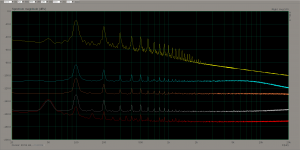
The first photo is of PSRR measurement. I set the scale to dBV this time, I also added the 1000x gain, I used 1x gain for the input ripple measurement, I connected the ADC directly to the filter cap through a 47uF cap.
The traces in the photo are as follows from top down:
- yellow trace - input ripple
- cyan trace - normal LM337
- orange trace - LM337+Cadj
- grey trace - LM337 + denoiser
- red trace - LM337 + dienoiser
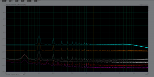
Second photo is in dBV/√Hz and traces are as follows from top down:
- cyan trace - normal LM337
- orange trace - LM337+Cadj
- grey trace - LM337+denoiser
- white trace - 1k resistor
- red trace - LM337 + dienoiser
- magenta trace - LNA input grounded.
I hope this set of measurements better represents the performance of the LM3x7 + de/dienoiser on the latest versions of the single boards. Since in my previous measurement the LM317 measured almost identically with LM337, even with the wrongly calibrated values, I presume these measurements are also an indicative of what to expect using the LM317 with the V1.4/V1.5 boards. I might as some point repeat this set of measurements for the LM317 as well.
I used LM337N from TI here.
I set my 0dB point correctly at 1300mV in ARTA. I made a zip file with each measurement with the value of interest, I only attached two photos to this post, in which I overlay all measurements for PSRR and noise.
The details of the measurement are as follows:
- The output capacitor is a Panasonic FR 470uF/25V with part number EEU-FR1E471LB. I recommend this capacitor for any LM337 +denoiser or dienoiser.
- Compensation network was 1x22nF + 2x10nF caps sandwiched, no R. I can't guarantee this value will work on other boards. But if you want to try add a 1R also. I was lazy to add it, I usually do. Seems to work fine without it for me.
- Input voltage around 18V, input caps 1x470uF and 1x100uF in parallel. 200R/1600R resistor combo for LM337 output voltage setting.
- 150R load resistor.
I also poked at the different denoiser nodes with metal tweezers and seems to recover nicely and fast.
I made a zip file with each individual measurement with the value of the signal of interest. The files with the N_ prefix are of the dBV/√Hz measurements. I attached here just two photos so to not be cluttered, and I overlayed all measurements in each.
The first photo is of PSRR measurement. I set the scale to dBV this time, I also added the 1000x gain, I used 1x gain for the input ripple measurement, I connected the ADC directly to the filter cap through a 47uF cap.
The traces in the photo are as follows from top down:
- yellow trace - input ripple
- cyan trace - normal LM337
- orange trace - LM337+Cadj
- grey trace - LM337 + denoiser
- red trace - LM337 + dienoiser
Second photo is in dBV/√Hz and traces are as follows from top down:
- cyan trace - normal LM337
- orange trace - LM337+Cadj
- grey trace - LM337+denoiser
- white trace - 1k resistor
- red trace - LM337 + dienoiser
- magenta trace - LNA input grounded.
I hope this set of measurements better represents the performance of the LM3x7 + de/dienoiser on the latest versions of the single boards. Since in my previous measurement the LM317 measured almost identically with LM337, even with the wrongly calibrated values, I presume these measurements are also an indicative of what to expect using the LM317 with the V1.4/V1.5 boards. I might as some point repeat this set of measurements for the LM317 as well.
I used LM337N from TI here.
Attachments
Last edited:
Have you tested your circuits with max load?
In the discrete regulator you only use 470uF is that big enough for input capacitor?
In the discrete regulator you only use 470uF is that big enough for input capacitor?
All tests were done at around 100mA, but I planned on testing a LM338 implementation at 3A, just that I need some time for the design/execution and measurement.
The input capacitor is up to you, you set that value based on your needs. Min Vin to regulator depends on the input capacitance and current output, transformer secondary voltage and its resistance. There is no recommended value for it. I recommend choosing a a value low enough that accounts for worst case scenario for mains sag, to have around minimum 2V extra for Vin vs Vout.
You can keep the capacitance as low as needed to get that minimum 2V drop across the regulator. Especially if you use the capacitance multiplier on pcbs that have it.
edit: the 470uF (+100uF from Cap multi circuit when I'd short the cap multi) for me resulted in the input ripple being at around 0dB before when I took only relative measurements. It was something convenient so I could read PSRR directly in dB from measurements, there's no other reason that I chose that value.
Last edited:
- Home
- Amplifiers
- Power Supplies
- D-Noizator: a magic active noise canceller to retrofit & upgrade any 317-based VReg