Let suppose if that amp has got short-circuit protection or similar like this for rails shorting to output node , then the fear of your pro world is not going to haunt that amp.......🙂
So no more offset discussion from now on......😀
BTW: I am happy with my Half Bridge amp with +/-180VDC rails.....with less than 40mV DC offset at output. Have you seen QSC PL8KW .........its Half-Bridge with rails touching almost +/-200VDC
So no more offset discussion from now on......😀
BTW: I am happy with my Half Bridge amp with +/-180VDC rails.....with less than 40mV DC offset at output. Have you seen QSC PL8KW .........its Half-Bridge with rails touching almost +/-200VDC
Ok then one nice question for you regarding floating Bridge.....
As far as i know in this topology there is single supply capacitor and the rails are floating. you can place a ground plane over the short length rail tracks or similar thing canbe done to reduce EMI, but the Filter cap's body is internally connected to negative rail , in your case its floating , wouldnot it will generate a good source of EMI then....
or i am lacking or missing something important.....🙂
Ground referenced bridge output should be grounded after differential output coil...So floating DC do not have any HF component..Or at least just a little...You should only have a ''pure'' DC floating PSU!
Fredos
Fredos
fredos said:Ground referenced bridge output should be grounded after differential output coil...So floating DC do not have any HF component..Or at least just a little...You should only have a ''pure'' DC floating PSU!
Fredos
I have seen a Rockford Fosgate Floating Bridge Class-D 1500W amp, whose rail filter capacitors were worst generators of EMI
fredos said:No I did'nt see the 8KW qsc schematics...You have it? 🙂
Fredos
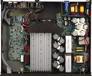
Not schematics, i have access to that amp.......😉
Attachments
i'm sorry for little offtopic, but think that this is interesting:
http://www.creelighting.com/products/power.asp.
does somebody have any opinion or try that nice (but expensive) stuff ?
http://www.creelighting.com/products/power.asp.
does somebody have any opinion or try that nice (but expensive) stuff ?
I've got 6 pieces of 1200 SiCs in the shelf since February. I still haven't measured them yet. We were at Fairchild's Power Seminar few months ago. We were advised to try Fairhild's new Stealth diodes, because SiC is very expensive (this is true), and they have a structural failure chance. They aren't as robust as bipolar diodes. But in a Class-D amplifier, maybe they should't have to be as robust as bipolar diodes...
Bender.ru said:i'm sorry for little offtopic, but think that this is interesting:
http://www.creelighting.com/products/power.asp.
does somebody have any opinion or try that nice (but expensive) stuff ?
heh, i have a handful, but 300-1200V is out of audio amp voltage range, actually, an ordinary Si shcottkys (cheaper&better) up to 250V are available.
It does not necessarily follow that 300 - 1200 V SiCs are out of Class-D audio range. I would make an FPGA-controlled amp. with paralleled output stages. Every output stage's supply current could be sampled at the desired time, and an inner control mechanism could equalize the currents through the digitally generated duty cycle (you can do anything in a digital PWM). Each output stages would be bridged, and consist of 4 pieces of 300 V IGBT from Fairchild, without antiparallel diode, and additional SiC schottkies antiparallel outside. I intended to parallel 4 output stages for one output. Finally I decided not to do it, because it would be so expensive, and I can't make a proper PCB layout. I think, IGBT and SiC co-pack would be the right choice.
imho ones (SiC) intend for AC-DC invertors, PFC or similar high voltage application...but price, that's something
 .
.
.new version for benders first D amp
Hi !
here is a new version for bender's first amplifier, with simplified phase shift and supplys. Comments for all are welcomed.
I want to drive with 500kHz triange. What changes must be made? I think the C6 (from comparator in), and the low pass filter must recalculated. Any sugestion for calculate the filter?
Thank u guys
Sorry for my poor english 🙂
Attachments
20955 has built-in level-shifter, also there is better OCP. You don't no need external timer (555) for shutdown driver, when OC occured.
I think that's no reson to apply 20124, if it possible to get 20955 🙂.
I think that's no reson to apply 20124, if it possible to get 20955 🙂.
ok bender! thanx. my local component dealer has 20955 so in short time i'll receive a few pcs. till then i will project some pcb's.
Gyula!
Once I used 600V SiC schottkys 2-3 years ago, because I had no other choice at that moment, but I strongly recommend you not to do the same! They are extremely weak and expensive, and only slightly faster then best pn diodes. And high voltage drop makes distortion higher!
Once I used 600V SiC schottkys 2-3 years ago, because I had no other choice at that moment, but I strongly recommend you not to do the same! They are extremely weak and expensive, and only slightly faster then best pn diodes. And high voltage drop makes distortion higher!
Hi, Fredos,
You use feedback after LC filter. Is it possible to use square wave clocking instead of triangle clocking?
http://www.google.com/patents?id=4WqcAAAAEBAJ&dq=square+wave+modulation+design
You use feedback after LC filter. Is it possible to use square wave clocking instead of triangle clocking?
http://www.google.com/patents?id=4WqcAAAAEBAJ&dq=square+wave+modulation+design
Is this a patent? Oh, ****! I designed and built some amps based on this principle before 2006, but I wouldn't believe in my wildest dream that this trivial nothing can be patented!
I posted here on 07-29-2005:
http://www.diyaudio.com/forums/showthread.php?s=&threadid=56827&perpage=25&pagenumber=2
(3rd reply)
This square vs. triangle clock thing is only a mathematical equivalency. Integration and summing are linear operators, so they are commutative. Thats the "big idea".
I posted here on 07-29-2005:
http://www.diyaudio.com/forums/showthread.php?s=&threadid=56827&perpage=25&pagenumber=2
(3rd reply)
This square vs. triangle clock thing is only a mathematical equivalency. Integration and summing are linear operators, so they are commutative. Thats the "big idea".
Funny how people play with word in the patents world...Feed a squared wave to an integrator is same as driving class d with triangle wave....I drive all my class d with a squared wave, that is feeded to an integrator...I could maybe patent it with different word...?
Fredos
Fredos
fredos!
Actually they are not the same, just equivalent (only in mathematical aspect)! In technical aspect they are different, since in the patented circuit there are fewer integrators (by 1)! But not the 10 cent less cost makes it better, but the possibility of driving channels from a central clock source without the risk of disturbation of clock, since square wave can be restored perfectly locally unlike triangle wave.
(But there is a drowback in this scheme too.)
You didn't answer lumanauw's question! Should I?
The question is: which integrator? The error amp? I don't think so!
Actually they are not the same, just equivalent (only in mathematical aspect)! In technical aspect they are different, since in the patented circuit there are fewer integrators (by 1)! But not the 10 cent less cost makes it better, but the possibility of driving channels from a central clock source without the risk of disturbation of clock, since square wave can be restored perfectly locally unlike triangle wave.
(But there is a drowback in this scheme too.)
You didn't answer lumanauw's question! Should I?
I drive all my class d with a squared wave, that is feeded to an integrator
The question is: which integrator? The error amp? I don't think so!
- Status
- Not open for further replies.
- Home
- Amplifiers
- Class D
- D AMP is back !!!