I’ve tested again and are getting different readings.
Multimeter set to 20v DC - black to ground and red to appropriate pins counting from left downwards then up on right hand side (groove of opamp at top) which I think is correct
Opamp NE5534
Pin 7 minus .73v
Pin 4 minus 2.10v
Opamp LF353
Pin 7 minus .73v
Pin 4 minus 2.10v
I’m really sorry for the confusion, I don’t know if it’s my testing or the thing is testing me ! Lol
Again, positive supply for phono is missing.
Thread merging may cause some additional
confusion, my post 15 was in reply to 13 ..
Thread merging may cause some additional
confusion, my post 15 was in reply to 13 ..
Again, positive supply for phono is missing.
Thread merging may cause some additional
confusion, my post 15 was in reply to 13 ..
Thank AS and apologies, my 1st time on a forum and I’m starting understanding the rules.
Do you mean the 2 voltage regulators (positive and negative ones)? and can you advise how to test please.
Thanks so much for input, greatly appreciated,
Schematic is in post 13.
Procedure is in post 12.
VR2, LM317, is one of the medium sized semiconductors with small heatsink.
Voltages about 35, 18 and 16.7 volts at the pins here.
Check C 63, 66 and 68 for polarity etc after "recapping".
A few posts deleted by moderation after thread merging.
Procedure is in post 12.
VR2, LM317, is one of the medium sized semiconductors with small heatsink.
Voltages about 35, 18 and 16.7 volts at the pins here.
Check C 63, 66 and 68 for polarity etc after "recapping".
A few posts deleted by moderation after thread merging.
Again, positive supply for phono is missing.
Thread merging may cause some additional
confusion, my post 15 was in reply to 13 ..
Unfortunately its not possible for any of us to alter the timeline of posts and so they always slot in to a thread in order of when they were created.
No easy way around that I'm afraid 🙂
Re post 21 it seems phono supply is completely missing -
if this measurement is real.
First of all learn how to apply a digital multimeter (again
I only assume it is one of this kind).
More will be destroyed shorting adjacent pins trying to do this.
Hard time fixing what has been a working amp before ..
if this measurement is real.
First of all learn how to apply a digital multimeter (again
I only assume it is one of this kind).
More will be destroyed shorting adjacent pins trying to do this.
Hard time fixing what has been a working amp before ..
Hi guys,
Sorry for the delay and once again I appreciate your help and patience.
I’ve followed your instructions (Mooly and AS) and can confirm that on VR2 there is 39v incoming an - 1v on output
I’m assuming the vr is at fault and that what there is no phono.
Let me know your thoughts.
Thanks, Jolson
Sorry for the delay and once again I appreciate your help and patience.
I’ve followed your instructions (Mooly and AS) and can confirm that on VR2 there is 39v incoming an - 1v on output
I’m assuming the vr is at fault and that what there is no phono.
Let me know your thoughts.
Thanks, Jolson
To be sure what is happening we really need four readings which are the input and outputs of the two regulators.
+39 in and -1 out as measured on the positive reg suggest a problem somewhere.
Are you measuring on the actual regulator pins themselves (be very careful not short them together).
You should see minus 39 volts on the input of VR1 and also minus 18 volts on its output.
I wouldn't be to quick to condemn the parts themselves, this could just as easily be a broken connection somewhere.
Also check the grounds are good. You should see no voltage on the grounds of the power supply as measured from the ground part of all the sockets on the back.
To be sure what is happening we really need four readings which are the input and outputs of the two regulators.
+39 in and -1 out as measured on the positive reg suggest a problem somewhere.
Are you measuring on the actual regulator pins themselves (be very careful not short them together).
You should see minus 39 volts on the input of VR1 and also minus 18 volts on its output.
I wouldn't be to quick to condemn the parts themselves, this could just as easily be a broken connection somewhere.
Also check the grounds are good. You should see no voltage on the grounds of the power supply as measured from the ground part of all the sockets on the back.
Thanks Mooly
I have just installed 2 new voltage regulators and I am now getting plus 18 and minus 18 on vr2.
A repair has been previously made to the middle pin of vr1 my means of a bridge. I’ll upload a pic, can you tell me if this bridged correctly?
I am getting 18v on the single opamp son pin 8 and 0v on pin 7, I don’t thimk that is correct
Last edited:
That's an awful mess of soldering. With the lighting casting shadows, its also difficult to see or guess just what is or isn't connected in your pic. The resolution is fine though, so try taking another pic with additional lighting from the direction of the bottom of the pic.
Again, inputs to the regs are about 40 volts, outputs 18 volts,
positive on VR2 and negative on VR1 - I refer to the schematic
in post 13 now.
You did not tell us that there was some other mischief going on
at the solder side of the regs before, only your "recapping". Of
course any help will fail if we do not know all the circumstances.
Generally, the regs LM 317, 337 will not fail easily, but if you short
pins I am not sure any more.
As announced earlier it is "easy" to measure input about 40 and
output 18, positive or negative respectively.
You did not tell us so far what kind of instrument you use and know
how to use it (I wrote about it before).
Re your post 33, the 18 volts will show up on pin 8 of dual and 7 of
single op amps and -18 on pin 4. Pin numbering was clear as far as
I can see.
It seems we are starting from zero, no, post 2 again ? Thanks.
Guys, you’ll be pleased to know we have success .... hooray.
I’ve learnt a lot with this little project (my 1st).
The fault was both voltage regulators. I took them out after around post 28, they where buggered and I replaced them, however I won’t lie, I put them in back to front. I then replaced them again and all is sounding beautiful.
Lessons I’ve learned is: be very careful when turning PCBs over, over and over again, I’ve obviously knocked the 30+ year vr’s when re-capping originally.
Thanks so much to Mooly and as. I’ll help you if your central heating ever goes wrong ! 🙂
AS, I’m using a fluke digital multimeter which is best suited for head engineer.
Thanks again.
Thanks... we are all electric (E7 storage heaters) 🙂
That PCB has seen a bit of action 😀 but the main thing is you found the problem and sorted it
That PCB has seen a bit of action 😀 but the main thing is you found the problem and sorted it
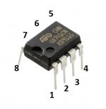
Be absolutely certain you are measuring the pins correctly. All have this configuration:
hi there mooly,you gave me some advice in the past on a philips cd player,
i hope you have been well? i hope that bug thats about these days has not gotten you,however im not so convinced the vaccine is ant better lol,
any way , i see you are familiar with this cyrus amp, cyrus two is its name in new zealand,
as in this thread i to am having troubles with the phono stage,im wondering if you could help me with the readings im getting,
the pic you put up regarding the leg numbers of the op amps was very helpful ,
me being me i dont do things by half so i have got the readings of all 6 ic's
a1, a2, a3, a4 are ne5534n .
a5, a6 are n5532n
here we go, readings are with power on, neg lead of dmm earthed to the phono earth, with selector on face of amp pointing to phono, from 1 to 8 as shown in your pic above
a1 . 1=16v 2=14.4v 3=15.4v 4=-18.08v 5=16v 6=18-15v 7=-0.064v 8=-0.684v
a2 . 1= 15.94v 2= 15.38v 3=15.38v 4= -18.08v 5= -0.610v 6= 0 7=18.15v 8=15.96v
a3 . 1=16.09v 2= -0.017v 3= -0.016 4= -18.08v 5= -0.802v 6= -0.173v 7=18.15v 8= 16.08v
a4 . 1= 16.07v 2= -0.016v 3= -0.015v 4= -18.08v 5= -0.791v 6= 0.165v 7=18.15v 8= 16.08v
a5 . 1= 0.077v 2= 0.001v 3= 0 4= -18.08v 5= 0 6= 0.001v 7= 0.001v 8=18.15v
a6 . 1= 0.118v 2= 0.001v 3=0 4= -18.08v 5=0 6= 0.001 7= 0.002v 8= 18.15v
vr1 and vr 2 were also a problem with these mans unit so a took reading from them aswell, these readings are taken from right to left with face toward me(id number)
vr1 right= -18.08v center = -35.11v left = -16.84v
vr2 right =35.05v center = 18.15v left = 16.89v
if you can see any thing strange with these readings it would be great to get a idea what you might think is going on
all the best
mike
maybe i am not right with model number as this thread is about a cyrus two v6?
if any one can tell me if this is not right ill start a new tread,
mike
if any one can tell me if this is not right ill start a new tread,
mike
- Home
- Amplifiers
- Solid State
- Cyrus Two V6 Phono Fault