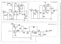
The first diagram is the actual circuit diagram for one channel. You will see the two upper sections, one called MM and and one MC. Which one of these is in use depends which inputs you are using, MM (the most common) or MC. MC has even higher gain than MM.
The output of these two circuits is selectable via the input selector switch. It connects one or the other to the following stage which is the lower one on that page and marked RIAA equalisation. That is another stage with gain.
CT will probably be 'centre or common terminal' but its not a common usage in this set up.
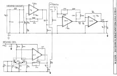
Now look at the next image. This is more of a block diagram than a complete circuit diagram. The output of MM and MC go to the 'end' terminals of a switch. The CT or centre terminal is the moving contact and that can select one or the other of these two stages.
The last image shows the input selector and how it selects all the different inputs. It is shown in the Phono position and the phono stage is set to MM. I've highlighted the signal path.
The balance control (shown on the last diagram) has the moving wiper of the pot connected to ground. Each end of the pot goes to the 'top' or input end of the volume control.
Notice the resistors R45 and R47. When the pot is turned to one end R47 is effectively connected to ground via the wiper. We now have R45 and R47 in series with each other and so the signal voltage at their junction (where the volume control gets its signal from) is reduced to less than half. This is why I say you should be hearing a change in level as you turn it.
With the control in the middle the volume control gets its signal via R45 and now the balance control adds its mid value setting of 50k plus R47 as an attenuating resistor... so now the signal level is equal for both channels.
Its just ohms law and a couple of resistors making an attenuator.
If you haven't a scope then you will have to begin by checking continuity from the RCA MM input to R17 on the MM input. Look at the diagrams to follow this.
Then check R15 at the MM output makes its way to R31/C19 of the RIAA section and finally that R43 connects to R45 when you select Phono.
Remember you can compare results between the two channels. The references numbers I have given may apply to the good channel anyway.
The output of these two circuits is selectable via the input selector switch. It connects one or the other to the following stage which is the lower one on that page and marked RIAA equalisation. That is another stage with gain.
CT will probably be 'centre or common terminal' but its not a common usage in this set up.
Now look at the next image. This is more of a block diagram than a complete circuit diagram. The output of MM and MC go to the 'end' terminals of a switch. The CT or centre terminal is the moving contact and that can select one or the other of these two stages.
The last image shows the input selector and how it selects all the different inputs. It is shown in the Phono position and the phono stage is set to MM. I've highlighted the signal path.
The balance control (shown on the last diagram) has the moving wiper of the pot connected to ground. Each end of the pot goes to the 'top' or input end of the volume control.
Notice the resistors R45 and R47. When the pot is turned to one end R47 is effectively connected to ground via the wiper. We now have R45 and R47 in series with each other and so the signal voltage at their junction (where the volume control gets its signal from) is reduced to less than half. This is why I say you should be hearing a change in level as you turn it.
With the control in the middle the volume control gets its signal via R45 and now the balance control adds its mid value setting of 50k plus R47 as an attenuating resistor... so now the signal level is equal for both channels.
Its just ohms law and a couple of resistors making an attenuator.
If you haven't a scope then you will have to begin by checking continuity from the RCA MM input to R17 on the MM input. Look at the diagrams to follow this.
Then check R15 at the MM output makes its way to R31/C19 of the RIAA section and finally that R43 connects to R45 when you select Phono.
Remember you can compare results between the two channels. The references numbers I have given may apply to the good channel anyway.
Attachments

hi there
sorry about not getting back to you regarding your valuable advice about the repair,
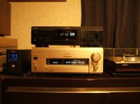
i have been at work and then went for a big drive (in my Peugeot 607) to pick up my new living room cd player,
what do you think of it,
its a sony cdp-xa50es,i have been looking for one for many years
it is the wrong colour but oh well
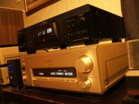
it fits in well with my da777es,ja-555es,dvp-s9000es and the ps-x700
next on the list is a za5es ,tc-ka7es,
some pics
what do you use for your stereo? i hope you dont mind me asking,
i collect sony gear,im always picking up other gear to find out what its like,i have hi hopes for the cyrus ,
oh i did say i had no turn table to try out the phono stage in the cyrus but i dont move my living room gear as its all very heavy and not willing to risk damage,
i have been testing the cyrus phono with a early 80's Belgium made philips,its a cheap and nasty thing but i seen it for next to nothing and its in the set for my philips cd-204 cd player, it works as it should after a few hours and a rebuild
but i ramble
mike
sorry about not getting back to you regarding your valuable advice about the repair,
i have been at work and then went for a big drive (in my Peugeot 607) to pick up my new living room cd player,
what do you think of it,
its a sony cdp-xa50es,i have been looking for one for many years
it is the wrong colour but oh well
it fits in well with my da777es,ja-555es,dvp-s9000es and the ps-x700
next on the list is a za5es ,tc-ka7es,
some pics
what do you use for your stereo? i hope you dont mind me asking,
i collect sony gear,im always picking up other gear to find out what its like,i have hi hopes for the cyrus ,
oh i did say i had no turn table to try out the phono stage in the cyrus but i dont move my living room gear as its all very heavy and not willing to risk damage,
i have been testing the cyrus phono with a early 80's Belgium made philips,its a cheap and nasty thing but i seen it for next to nothing and its in the set for my philips cd-204 cd player, it works as it should after a few hours and a rebuild
but i ramble
mike
Attachments
Last edited:
my frist discs to spin were enya and mark knopfler local hero in HDCD (i dont know if much to be gained) ,out standing sound as i hear it,its different to the dvp-s9000es i have been using ,
any way ill do my best on the cyrus after work tomorrow, its almost one in the morning here, have a good day
any way ill do my best on the cyrus after work tomorrow, its almost one in the morning here, have a good day
Nice machine 🙂 I've always liked Sony gear.
I mainly use a Marantz Pearl-Lite SACD, Sony Minidisc and DAB radio (Pure DRX701ES). Amp is a lateral FET design of my own partnered with B&W703's.
I mainly use a Marantz Pearl-Lite SACD, Sony Minidisc and DAB radio (Pure DRX701ES). Amp is a lateral FET design of my own partnered with B&W703's.
The first diagram is the actual circuit diagram for one channel. You will see the two upper sections, one called MM and and one MC. Which one of these is in use depends which inputs you are using, MM (the most common) or MC. MC has even higher gain than MM.
The output of these two circuits is selectable via the input selector switch. It connects one or the other to the following stage which is the lower one on that page and marked RIAA equalisation. That is another stage with gain.
CT will probably be 'centre or common terminal' but its not a common usage in this set up.
Now look at the next image. This is more of a block diagram than a complete circuit diagram. The output of MM and MC go to the 'end' terminals of a switch. The CT or centre terminal is the moving contact and that can select one or the other of these two stages.
The last image shows the input selector and how it selects all the different inputs. It is shown in the Phono position and the phono stage is set to MM. I've highlighted the signal path.
The balance control (shown on the last diagram) has the moving wiper of the pot connected to ground. Each end of the pot goes to the 'top' or input end of the volume control.
Notice the resistors R45 and R47. When the pot is turned to one end R47 is effectively connected to ground via the wiper. We now have R45 and R47 in series with each other and so the signal voltage at their junction (where the volume control gets its signal from) is reduced to less than half. This is why I say you should be hearing a change in level as you turn it.
With the control in the middle the volume control gets its signal via R45 and now the balance control adds its mid value setting of 50k plus R47 as an attenuating resistor... so now the signal level is equal for both channels.
Its just ohms law and a couple of resistors making an attenuator.
If you haven't a scope then you will have to begin by checking continuity from the RCA MM input to R17 on the MM input. Look at the diagrams to follow this.
Then check R15 at the MM output makes its way to R31/C19 of the RIAA section and finally that R43 connects to R45 when you select Phono.
Remember you can compare results between the two channels. The references numbers I have given may apply to the good channel anyway.
hi there
i have spent some time testing the caps and resistors in the riaa and mc and mm amps ,all seems good with no failures,i think ill pull the transistors and see if i can test them,i never trust transistors as they have given me trouble in many other things in the past,
being a twin transistor pack so to speak ,do i just test as a single transistor x2? how will i know which leg are from each transistor?
or shall i just replace both of them and be done with it?
i like you speakers ,they are nice and beefy looking ,any gear made by b and w is great i have found,i have some dm7's and sadly sold my dm2a's a few years back ,i regret that
mike
Nice machine 🙂 I've always liked Sony gear.
I mainly use a Marantz Pearl-Lite SACD, Sony Minidisc and DAB radio (Pure DRX701ES). Amp is a lateral FET design of my own partnered with B&W703's.
i have taken every cap out in the whole phono stage and tested them ,tested every resistor and not found ant failed components ,i wish i had ordered the caps so i could have just replaced them as i went,but we live and learn ,
i reflowed the selector switch once i got to it and that is all ok ,i found no burnt tracks or bad solder joints,
im starting to think this one might bet me, im going to take those twin transistors out and have a go at testing them,im guessing as you would a normal one,
i like working on the power amp part as you can see whats wrong by just taking a smell most the time, find the burnt bit and work back till into the amp till things start testing right haha, it feels like im chasing ghosts on this one,
could you give any advice where to test with the power on? some voltage points to test for my problem? my dmm is not a fancy one but should be ok im thinking for the low voltage of the mc and mm stage ,are there lower voltages than the ic testing we did?
i was hoping it was a opamp,
i recapped my sony cdp-302es when i got it,it was not working on one channel and i was worried about this ,
i tested all resistors and still nothing ,so i changed out all the op amps and it works great now,i know this is not the way to fix things but it has worked for me in the past,
i am starting to follow the flow so to speak but i just cant seem to work it out,if i test it running i should be able to see where the flow blockage is ,
would i earth the neg on dmm as i did testing the ics ,measure the voltage before and after every resistor till i find a difference to the working side,this way it would tell me the im close would it not?
or will this damage it further?
mike
Nice machine 🙂 I've always liked Sony gear.
I mainly use a Marantz Pearl-Lite SACD, Sony Minidisc and DAB radio (Pure DRX701ES). Amp is a lateral FET design of my own partnered with B&W703's.
your marantz would be a great sacd player would it not,i use my dvp-s9000es for sacd's ,i only have one hahaha ,what model mini disc do you have?i like mini disc ,my ja-555es is super,
i have been listening to my new xa50es and i like it better to my s9000es for cds,
about your amp,lateral fet,is it a class a? i picked up a musical fidelity studio t
the other week ,i thought the fets would have been damaged but lucky enough the wire wound resistors had all burnt out and the fets were still ok, i set the bias at 10mv as it was running HOT ,some one had it at around 40mv per amp pcb ! ,its meant to be higher then 10 according to the web sites that chat about them but it sounds ok the way it is ,
it just lives under my bed any way hahaha,
why i ask about your amp,is your design similar to this one?as it has fets ,sorry if i sound dumb but i thought it was worth asking,
it sounds as you have a great system
mike
You have to be logical 🙂
Earlier you mentioned that the fault is apparent on both MM and MC inputs. So that in one go rules out the section with the dual transistor because that isn't used for the MM input.
Given that both inputs (MM and MC) appear faulty it would be a pretty safe bet to assume that actually 'neither is faulty' and the issue lies elsewhere and further along the chain.
For a fault like this you really should use an oscilloscope, it just makes it all so easy.
Without a scope and basic checks (which you have done) are that the opamp supplies are good and that all opamp output pins are close to zero volts DC.
That proves the DC conditions are basically correct.
You could try injecting a signal into the audio path if you can't get hold of a scope... or (with caution) apply a line level signal to the MM input and 'jump' the signal through the various stages with a jumper lead and see where the audio goes missing.
Removing and replacing parts in hope isn't recommended and can do more harm than good'. Always try and diagnose a fault with the minimum of intervention by measurement and diagnostics alone.
The LatFet amp is this one, Class AB:
My MOSFET amplifier designed for music.
Post #283 onward:
Post your Solid State pics here.
My MOSFET amplifier designed for music.
Post #283 onward:
Post your Solid State pics here.
You have to be logical 🙂
Earlier you mentioned that the fault is apparent on both MM and MC inputs. So that in one go rules out the section with the dual transistor because that isn't used for the MM input.
Given that both inputs (MM and MC) appear faulty it would be a pretty safe bet to assume that actually 'neither is faulty' and the issue lies elsewhere and further along the chain.
For a fault like this you really should use an oscilloscope, it just makes it all so easy.
Without a scope and basic checks (which you have done) are that the opamp supplies are good and that all opamp output pins are close to zero volts DC.
That proves the DC conditions are basically correct.
You could try injecting a signal into the audio path if you can't get hold of a scope... or (with caution) apply a line level signal to the MM input and 'jump' the signal through the various stages with a jumper lead and see where the audio goes missing.
Removing and replacing parts in hope isn't recommended and can do more harm than good'. Always try and diagnose a fault with the minimum of intervention by measurement and diagnostics alone.
i can get a oscilloscope but i have no idea how to use it ,i have had some one try to show me once on some thing he was repairing ,but i guess i better go and see if i can learn ,
ill report back
thats a cool looking amp and the rest looks just as nice
what is the spec on the amp?
Its all in the threads 🙂
i can get a oscilloscope but i have no idea how to use it ,i have had some one try to show me once on some thing he was repairing ,but i guess i better go and see if i can learn ,
ill report back
An oscilloscope is really just a voltmeter that traces out voltage with respect to time and so allows you to look in real time at signals and their levels within the circuitry. It makes it possible to trace a signal through the circuit.
- Home
- Amplifiers
- Solid State
- Cyrus Two V6 Phono Fault