Good evening guys.
I am hoping someone can help me with a problem?
On Wednesday I totally re-capped my old Cyrus 2 amp. What I did do is change all the caps for non polarized caps. Everything worked fine and sounded great. I then realized that some of the caps are polarized and wanting to keep the unit original I replaced the caps that should be polarized with the correct caps, paying attention to polarity. Since doing this the phono line has stopped working completely, all other inputs are fine. Please can someone guide me in the direction to diagnose the problem.
I am a novice in this area so any help is much appreciated. Thanks so much
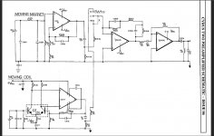
First steps are to check the supplies to the phono stage. The circuit I have shows both dual and single opamps and so the positive supply pins differ for each. Pin 7 for the singles and pin 8 for the duals. Pin 4 is the same for both.
So measure the supplies on each opamp. You should see PLUS 18 on the positive supply and MINUS 18 for the negative.
Next look at the output pins of each opamp. They should all read very close to zero volts DC.
So measure the supplies on each opamp. You should see PLUS 18 on the positive supply and MINUS 18 for the negative.
Next look at the output pins of each opamp. They should all read very close to zero volts DC.
Attachments
Phono input on both channels? That could be the power supply to the phono preamps since its shared - perhaps you accidentally shorted out one of the rails, or created a break in the supply. Could you have left some connector unplugged by mistake (can't find an image of the internals, no idea how its arranged).
First steps are to check the supplies to the phono stage. The circuit I have shows both dual and single opamps and so the positive supply pins differ for each. Pin 7 for the singles and pin 8 for the duals. Pin 4 is the same for both.
So measure the supplies on each opamp. You should see PLUS 18 on the positive supply and MINUS 18 for the negative.
Next look at the output pins of each opamp. They should all read very close to zero volts DC.
Thanks Mooly, could you advise how to test and at which points please, I have a multimeter
Cap replacement - so called "recapping" does a lot of harm to new and vintage gear
Surely making mistakes is what does damage - failing caps can damage other parts, new caps should be good for a few decades. Replacing lots of caps is often tricky work and involves significant disruption to an amplifier, so care is needed to restore and replace all the connections/connectors and ensure they are solid as well as getting the caps replaced right.
Unfortunately electrolytics are effectively consumables, even the best, though it is wise to assess the state before committing to a full recap. Filter caps often see significantly more temperature than other caps due to high ripple and are the first suspects to test and perhaps replace. If an amp has seen 20 years hard duty at high temps you should assume all the caps are aging, if its only seen very light use they may be good for another few decades...
Failing to recap can lead to oscillation in solid state amps, which can be destructive to amp and speakers.
Thanks guys.
This is where I’m at: I hadn’t realized when testing opamp that I should of been testing for ac, I have tested now but can someone confirm I’m doing it correctly, I placed black probe on neutral of PSX input and red on pins as recommended above, is the the correct method and if so I am getting 0 voltage, please can anyone advise where to go next.
Thanks so much
MT : in Cyrus 2 only four caps need to be checked even after decades of hard use.
JH : black wire of your multimeter goes from MM "Com" to black speaker terminal
of amp. Address test points with the red wire. I assume this is a Digital MM.
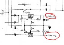
Check for dc voltage, because positive phono supply is missing if you only
see negative voltages here.
JH : black wire of your multimeter goes from MM "Com" to black speaker terminal
of amp. Address test points with the red wire. I assume this is a Digital MM.
Check for dc voltage, because positive phono supply is missing if you only
see negative voltages here.
PS phono supply is separate, four rectifier diodes, two elcaps (expect the same voltage
here as in the power amp) and integrated regulators, arriving at plus and minus 18 volts.
here as in the power amp) and integrated regulators, arriving at plus and minus 18 volts.
Thanks guys.
This is where I’m at: I hadn’t realized when testing opamp that I should of been testing for ac, I have tested now but can someone confirm I’m doing it correctly, I placed black probe on neutral of PSX input and red on pins as recommended above, is the the correct method and if so I am getting 0 voltage, please can anyone advise where to go next.
Thanks so much
You are measuring DC voltages in the power supply, not AC.
Place the black meter lead on ground and measure the DC voltage on the appropriate pins.
The parts lists mentions NE5534 opamps. Those are singles and so you should have plus 18 volts on pin 7 of each one and minus 18v on pin 4 of each.
The LF353 are dual opamps and while pin 4 remains the same, the positive is now on pin 8.
The output pin of each opamp should be zero volts DC. That is pin 6 for the NE5534 and pins 1 and 7 for the LF353.
In the power supply you need to check the two supplies here. Look for plus 18 at the top and minus 18 at the bottom.
Attachments
Cyrus 2 - ongoing phono saga
Been having trouble with the phono stage on my Cyrus 2 (v6).
Initially no audio at all at phono stage, traced problem to broken pin and cracked joint on voltage regulators.
So, got power to phono now but no audio, just loud hum!
Any ideas guys?
Been having trouble with the phono stage on my Cyrus 2 (v6).
Initially no audio at all at phono stage, traced problem to broken pin and cracked joint on voltage regulators.
So, got power to phono now but no audio, just loud hum!
Any ideas guys?
Thank you for illustrating post 11 and 12.
Cyrus is a shrinked amp, so we should inflate the coverage.
OP moved on to a new thread - why ?
Cyrus is a shrinked amp, so we should inflate the coverage.
OP moved on to a new thread - why ?
 Threads merged.
Julian... please don't start multiple threads for the same issue. It gets confusing and just causes others to go over ground already covered.
Julian... please don't start multiple threads for the same issue. It gets confusing and just causes others to go over ground already covered.
Mooly, that’s no problem and apologies. Thanks for pointing out
Thanks for all of this help, I’m learning quickly.
Mooly, I’ve tested op apps as detailed and have found the following dc voltages:
Pin 7 = 42v
Pin 8 = 39v
Pin 6 MC = 38v
Pin 6 MM = 27v
Pins 1,2,3 and 4 = .8v
Mooly, I’ve tested op apps as detailed and have found the following dc voltages:
Pin 7 = 42v
Pin 8 = 39v
Pin 6 MC = 38v
Pin 6 MM = 27v
Pins 1,2,3 and 4 = .8v
Please ignore my previous test results. Making myself look an idiot here !
Test results for op amps
Singles pin 7 = 20v
Singles pin 4 = .7v
Singles pin 8 = 19v
All outputs have up to 18v
Test results for op amps
Singles pin 7 = 20v
Singles pin 4 = .7v
Singles pin 8 = 19v
All outputs have up to 18v
- Home
- Amplifiers
- Solid State
- Cyrus Two V6 Phono Fault