R81 bias setting resistor, what are the adjacent posts ?
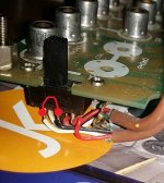
adjacent to R81 are two looped wires with ceramics round them.
Is this anything to do with the bias ?
Just an aside, I just thought they look handy and no idea what they do, no component # on the board that I can see ?
I'm just about to pull R81 and attempt to squeeze in the 2k5 bourns pot.
excited/scared face
Attachments
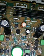

The resistor looks OK.
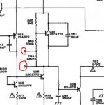
Those loops appear to connect to R81 and in fact are marked in an obscure way on the circuit diagram. The only function they serve is to allow another resistor to be added in parallel which would increase the final bias current. This is the problem with fixed settings... they are so dependent on the actual characteristics of the semiconductors used and so each amplifier will be slightly different. Swap the semiconductors and they will be a lot different.
You can snip that resistor out (R81) and then having first set the preset to maximum resistance tag it across the pins. That leaves the 680 ohm in circuit.
Attachments
I was hoping you'd say that! seems when they decided to remove the bias adjustment they added service posts 🙂The resistor looks OK.
Those loops appear to connect to R81 and in fact are marked in an obscure way on the circuit diagram.
You can snip that resistor out (R81) and then having first set the preset to maximum resistance tag it across the pins. That leaves the 680 ohm in circuit.
yay 🙂
is there anything to stop me just leaving the preset in place once the bias is adjusted ? ir do i need to fit a new R81 in the form of a normal resistor?Yes. I've just added to the post above (refresh the page 🙂)
Leave the preset in place everytime. It would be very difficult to make up (for example) a 763 ohm or whatever value the preset is finally tweaked to.
Fixed bias amps are in a minority, and the only reason has to be to save on a manual adjustment on the production line.
Fixed bias amps are in a minority, and the only reason has to be to save on a manual adjustment on the production line.
excellent thats also good news. what can possibly go wrong ...Leave the preset in place everytime. It would be very difficult to make up (for example) a 763 ohm or whatever value the preset is finally tweaked to.
Fixed bias amps are in a minority, and the only reason has to be to save on a manual adjustment on the production line.
only slight hiccup is i could only replace the drivers on the burned out channel. So the other side has new outputs a new dual resistor but the original drivers (all the ore drivers tested ok btw)
We have to take things slowly, there are lots of potential pitfalls on the way 🙂
So... the other (good) channel now has new outputs fitted ? Thats a possible issue as far as the bias goes because it won't be correct with the fixed set up in place.
It might be best for you to snip the 130 ohm (R81) in the good channel to force zero bias and then we can worry over that later after the zapped channel is hopefully fixed.
yes no worries. I was planning to zero bias and preset the other channel too. can't take anything for granted !We have to take things slowly, there are lots of potential pitfalls on the way 🙂
So... the other (good) channel now has new outputs fitted ? Thats a possible issue as far as the bias goes because it won't be correct with the fixed set up in place.
It might be best for you to snip the 130 ohm (R81) in the good channel to force zero bias and then we can worry over that later after the zapped channel is hopefully fixed.
pitfalls such as ? .... 😱yes no worries. I was planning to zero bias and preset the other channel too. can't take anything for granted !
He he 🙂
Oh, just things... but hopefully if you work through it all carefully and checking along the way then we should get a good result. The thing you learn is never to take anything for granted.
So no solder blobs that have fallen on the print, all replacement parts correctly fitted 😉 no mixup of NPN's and PNP's. No stray strands of solder braid lurking.
And that's just the easy stuff 😀
I'll look in later.
cheers fella i did paranoidly check my soldering wasn't shorting tracks !He he 🙂
Oh, just things... but hopefully if you work through it all carefully and checking along the way then we should get a good result. The thing you learn is never to take anything for granted.
So no solder blobs that have fallen on the print, all replacement parts correctly fitted 😉 no mixup of NPN's and PNP's. No stray strands of solder braid lurking.
And that's just the easy stuff 😀
I'll look in later.
and remember to keep using the Mains Bulb Tester to power ON every time you make any modification.
Prove it is not going to blow up, BEFORE you apply direct mains power.
Prove it is not going to blow up, BEFORE you apply direct mains power.
I doubt I'll be brave enough to go full mains today. need to feel absolutely sure I've measured the bias correctly first.and remember to keep using the Mains Bulb Tester to power ON every time you make any modification.
Prove it is not going to blow up, BEFORE you apply direct mains power.
btw I can't help noticing the phono signal runs through wires to a crappy looking switch! ? could i bypass that somehow ? it'll be MM for the forseeable futureand remember to keep using the Mains Bulb Tester to power ON every time you make any modification.
Prove it is not going to blow up, BEFORE you apply direct mains power.
setting the bias will make the MBT filament glow.I doubt I'll be brave enough to go full mains today. need to feel absolutely sure I've measured the bias correctly first.
A very low wattage bulb will glow more brightly than a higher wattage bulb.
There will be no harm in startng with a very low wattage bulb. try a 28W
and move up in steps as each proves there is no disastrous fault.
You may have to go as high as 100W to get near working voltage when the bias has been set.
Can you post a pic showing the detail?btw I can't help noticing the phono signal runs through wires to a crappy looking switch! ? could i bypass that somehow ? it'll be MM for the forseeable future
I doubt I'll be brave enough to go full mains today. need to feel absolutely sure I've measured the bias correctly first.
When you get as far as powering it up with a bulb, and if all seems OK and the bias adjusts OK then be sure to turn it back down to zero again before trying full mains.
This is because the bulb will cause the rails to be a bit low and that in turn will mean the bias will increase as the rails come back up to full value.
In simulation a bias setting giving 24 ma on reduced -/+ 20 volt rails gives nearer 40 ma on -/+ 30 volts.
That is a bit of an average looking switch. To bypass it you simply short the middle pin to whichever end pin the switch is turned toward. Do that for both sides of the switch.
Attachments
- Home
- Amplifiers
- Solid State
- Cyrus 1 output transistor question. push-pull?