unhinged said:Can someone tell me what phenolic strips are? This book's (Tab Electronics Guid to Understanding Electricity and Electronics) talks about getting phenolic strips to mount the capacitors to in the case. I've looked all over and can't find these. I don't even know what they are.
Hello, welcome back 🙂
B&W use phenolic resin in their nautilus range quite a lot for the enclosures (it's that really shiny plastic stuff), as do a few other manufacturers. I guess it must be very dense and a very 'dead' material (doesnt ring much), though Ive never handled some so i don't really know, so I suppose that mounting caps onto a strip of this may help to reduce the effects of microphonics? A little like those rubber ring valve dampers perhaps.
Steve
This is the exact text: ...three phenolic-type, 2-lug solder strips... these are specified only because they are inexpensive and effective. If your local electronics parts store doesn't have these in stock, there are many good alternatives. Any method of providing three chassis mountable, insulated tie points that will hold the filter capacitors firmly in place, and allow easy connections to the capacitor leads, will function equally well.
Does that make it any clearer? I'm happy to go with any alternative but this is kind of the issue I started the thread with, I don't really know how these things should be mounted properly. Not being able to find an example of what he's describing isn't helping. I'm sorry I'm being so useless here, I'd like to get this right from the start especially as this is a power supply and I'm fairly weary of playing with mains electricity as it is.
Does that make it any clearer? I'm happy to go with any alternative but this is kind of the issue I started the thread with, I don't really know how these things should be mounted properly. Not being able to find an example of what he's describing isn't helping. I'm sorry I'm being so useless here, I'd like to get this right from the start especially as this is a power supply and I'm fairly weary of playing with mains electricity as it is.
Any method that holds the caps down, and prevents shorting, will work. A lot of manufacturers simply glue the caps to the circuit board.
I use a dab of hot glue.
Are you using a board?
When was that book written?
E
I use a dab of hot glue.
Are you using a board?
When was that book written?
E
I've been reading through this and similar threads and find them very interesting. I started off a few months looking into how I can have build "high end" audio enclosures, but using them for computers instead for the htpc market.
Going to the shops I found out, working on a small budget is not easy, especially when you want extrusions and paneled chassis with heatsinks done in small quantity.
Anyway to not go off topic I have two questions, hopefully in line with the nature of this thread.
Are there ways, tools, machines for the home shop I can use to make an extrusion. One example would be some front panels that have a wave or grooves in them. The other extrusion that I find very nice are the corner "standoffs" on the Wadia 861
Sorry I hit the wrong button and dont' see an edit button.
The second question though, wondering if there any books the experts here would recommend regarding metalworking in the context of chassis / enclosures.
Thank you,
Stuart
The second question though, wondering if there any books the experts here would recommend regarding metalworking in the context of chassis / enclosures.
Thank you,
Stuart
StuartAmbient said:Are there ways, tools, machines for the home shop I can use to make an extrusion. One example would be some front panels that have a wave or grooves in them. The other extrusion that I find very nice are the corner "standoffs" on the Wadia 861
I doubt they're extrusions, for $20000 odd that player costs Id expect them to machined (on a lathe) from solid bar.
For front panels, I guess you'd want maybe 1/4" solid ally sheet, and mill any shapes into that you wanted. I think I've got the right end of the stick there.
Steve
Attachments
![wadia_861[1].jpg](/community/data/attachments/12/12448-dc5b6429764069950eaf267d9d839368.jpg?hash=3FtkKXZAaZ)
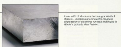
Sweeeeeeeeeet!!! Thats the kind of engineering I appreciate. I haven't really looked into wadia much until today after stuart brought them up. Definitely something to aspire to anyway!Even the Wadia chassis is machined from a solid block of aluminum.
Steve
Peter Daniel said:Even the Wadia chassis is machined from a solid block of aluminum.
Is that true ? That is amazing.
Stuart
For looks my favourite "milled from solid" component is Linn's Sondek CD12 CD player. See www.linn.co.uk
James
James
Very clean, Chipco. Very.
That is the first sink I've seen that addresses the "ringing" issue well. Does it sound as "dead", when you strum it, as it looks?
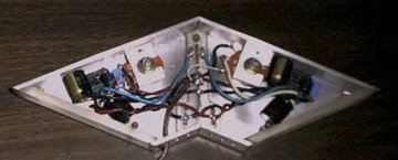
Listened to mine last night, looks like it is worth finishing. Oughta give you all a chuckle...
Happy Easter all!😉
E
That is the first sink I've seen that addresses the "ringing" issue well. Does it sound as "dead", when you strum it, as it looks?
Listened to mine last night, looks like it is worth finishing. Oughta give you all a chuckle...
Happy Easter all!😉
E
Attachments
ekd said:That is the first sink I've seen that addresses the "ringing" issue well.
Is ringing much of a problem then in heatsinks? Is it the actual noise that the fins create by themselves that's a problem? Or is it microphonics? In either case, perhaps an improvement would be pyramid shaped 'fins' or prongs, though this would be harder to machine, should be possible with a tilting table of some kind though. Could another option be to bolt on another plate to the 'unnatatched' end of the prongs, to increase the rigidity of them but keep the surface area?
Steve
All I know about this...
will fit in a thimble. Someone please correct me...
"Is ringing much of a problem then in heatsinks?"
It can be. The enemies of electronics are heat and vibration. As to sonic degradation in amps, I have so little experience as to render me incapable af claiming that I can hear "ringing". However, it's a good idea to eleminate it simply based on the fact that a bit of design work will take care of it at little or no cost.
"Is it the actual noise that the fins create by themselves that's a problem? Or is it microphonics?"
It is picked up by the sink from the environment. Think of it like this. The reason that a tuning fork works so well is that it has 2 parts that are as equal a length and thickness (and material) as possible. This sets up harmonics when 1 tine is struck (the second one feeds off of the vibrations in the other), that keep the note going. Any thing with parallel and equal parts "rings" much more than anything that doesn't.
Is the shape of my second amp starting to make sense?
"In either case, perhaps an improvement would be pyramid shaped 'fins' or prongs, though this would be harder to machine, should be possible with a tilting table of some kind though."
You are not as stupid as I look. Even varying the thickness of the fins will kill harmonics. It just looks bad. The best shape for any audio housing would resemble a cowpie dropped at cruising speed (about 3mph). You want that in your living room?
"Could another option be to bolt on another plate to the 'unnatatched' end of the prongs, to increase the rigidity of them but keep the surface area?" Yes, and it would work especially well if it was made from a dis-similar material (yeah the wood is pretty, but it's workin' right now).
Remember, the whole housing is "prongs".
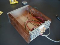
Hence my acrylic panels connecting the channel walls. The cooling fins on every two stroke street bike I have ever seen have "rubber" wedges placed, in an asymetrical pattern, between them. They are "clamped", and you are correct.
Somebody take it from here?
E
will fit in a thimble. Someone please correct me...
"Is ringing much of a problem then in heatsinks?"
It can be. The enemies of electronics are heat and vibration. As to sonic degradation in amps, I have so little experience as to render me incapable af claiming that I can hear "ringing". However, it's a good idea to eleminate it simply based on the fact that a bit of design work will take care of it at little or no cost.
"Is it the actual noise that the fins create by themselves that's a problem? Or is it microphonics?"
It is picked up by the sink from the environment. Think of it like this. The reason that a tuning fork works so well is that it has 2 parts that are as equal a length and thickness (and material) as possible. This sets up harmonics when 1 tine is struck (the second one feeds off of the vibrations in the other), that keep the note going. Any thing with parallel and equal parts "rings" much more than anything that doesn't.
Is the shape of my second amp starting to make sense?
"In either case, perhaps an improvement would be pyramid shaped 'fins' or prongs, though this would be harder to machine, should be possible with a tilting table of some kind though."
You are not as stupid as I look. Even varying the thickness of the fins will kill harmonics. It just looks bad. The best shape for any audio housing would resemble a cowpie dropped at cruising speed (about 3mph). You want that in your living room?
"Could another option be to bolt on another plate to the 'unnatatched' end of the prongs, to increase the rigidity of them but keep the surface area?" Yes, and it would work especially well if it was made from a dis-similar material (yeah the wood is pretty, but it's workin' right now).
Remember, the whole housing is "prongs".
Hence my acrylic panels connecting the channel walls. The cooling fins on every two stroke street bike I have ever seen have "rubber" wedges placed, in an asymetrical pattern, between them. They are "clamped", and you are correct.
Somebody take it from here?
E
Does it sound as "dead", when you strum it, as it looks?
Like strumming barstock... They're 3/8" square protrusions, 5/8" long. Real dead.
The photo doesn't do justice to the walnut.
Let me clarify...
Remember, the whole housing is "prongs". * In this dogfight, anyway...*
And Chipco's sink rings like he((. Bet on it.
But,
I'll bet it's at such a high frequency, that we'll never hear it. Directly, or through the chip.
E
Remember, the whole housing is "prongs". * In this dogfight, anyway...*
And Chipco's sink rings like he((. Bet on it.
But,
I'll bet it's at such a high frequency, that we'll never hear it. Directly, or through the chip.
E
Hey, Chip!
We posted at the same time.
As to the looks...
I'm betting on it. Cameras suck, especially mine... (got nothin' to complain about though, it's 10 yrs old... 😉 )
Couple of these kids got real brains on 'em, eh?
E
We posted at the same time.
As to the looks...
I'm betting on it. Cameras suck, especially mine... (got nothin' to complain about though, it's 10 yrs old... 😉 )
Couple of these kids got real brains on 'em, eh?
E
More clarification...Jeez!
The better Chipco is at machining things (wanna make a bet? grab your mikes! My lunch is on C...) the more parallel and equal his parts (prongs) are.
We need a "Guru" to tell us exactly when the frequencies become meaningless. That way we can fight amongst ourselves about that, and (if we are lucky!) avoid the whole "direction of the wire" thing altogether... 😀
Have one for me, boys... I'm fixin' to check out, and do the same for you!...
E
- Status
- Not open for further replies.
- Home
- General Interest
- Everything Else
- Cutting, drilling, mounting etc. for the absolute beginner