Well, it's not really audio, more for hf work, but is interesting (I do not claim to fully understand it, though).
Inventor is Bruce Hofer, the guy who designed (with Richard Cabot) the Audio Precision System One and Two. These systems are literally packed with patents specifically invented to solve problems of generating and analysing audio signals with less than -120dB distortion between 10Hz and 100kHz. Transformer coupled, that is! Reading those manuals makes you quite humble..
Jan Didden
Attachments
And what was the name of your university again? Does it support this name?
And what was then name of the textbook you studied? Does it support this name?
And what was the name of your professor? Does he/she support this name?
And what is blueberry doing in the sky; I thought it Lucy was there?
🙂
\Jens
And what was then name of the textbook you studied? Does it support this name?
And what was the name of your professor? Does he/she support this name?
And what is blueberry doing in the sky; I thought it Lucy was there?
🙂
\Jens
Re: 'feedbeside' amplifier topologies
That’s not that difficult. You have to feed your amp something, otherwise it turns out to be a nop-amp (no operational amplifier). Hell, who has ever invented the name “op-amp” (operational amplifier)? Must be an ancient DIY with not much luck in building a working amplifier.
Cheers 😀
dimitri said:
*********** what topologies?
That’s not that difficult. You have to feed your amp something, otherwise it turns out to be a nop-amp (no operational amplifier). Hell, who has ever invented the name “op-amp” (operational amplifier)? Must be an ancient DIY with not much luck in building a working amplifier.
Cheers 😀
millwood said:for your terminology fighters, here is another schematic. can you tell if it is vfb or cfb or none of them?
It corresponds to what the industry refers to as a current
feedback op amp in that it has a low impedance negative
feedback input - the emitters of the (buffered) input transistors.
Whether this is a proper definition has been hashed elsewhere.
😎
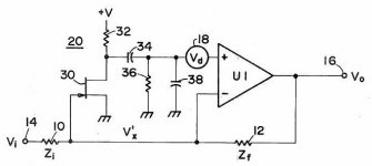
While on the topic of Current feedback opamps.
Can I model the opamp like this?
And just set Rin2 = 50 ohm and Rin1 = oo
\Jens
Can I model the opamp like this?
An externally hosted image should be here but it was not working when we last tested it.
And just set Rin2 = 50 ohm and Rin1 = oo
\Jens
Nelson Pass said:It corresponds to what the industry refers to as a current
feedback op amp in that it has a low impedance negative
feedback input - the emitters of the (buffered) input transistors.
😎
Nelson, why don't you give us amature EE types some chance to get the answer right? 🙂.
Yes, it is a cfb amp (LT1210).
For those of you looking for a high-performance headphone amp or even a small power amp, check out that sucker: 1.1a output current, 35mhz bandwidth, 900v/us slew rate, stable with capacitive loads, and in a to220 package. I tried one and loved it.
JensRasmussen said:Can I model the opamp like this?
\Jens
you sure can model it like that, Jens. Whether it is correct remains to be seen.
on the topic of current feedback amplifiers, has anyone tried to use a current buffer following a CFB? performance-wise, it is hard to beat but probably tough to control DC offset.
I will find out my lt1210 and try it out this weekend.
I will find out my lt1210 and try it out this weekend.
JensRasmussen said:While on the topic of Current feedback opamps.
Can I model the opamp like this?
An externally hosted image should be here but it was not working when we last tested it.
And just set Rin2 = 50 ohm and Rin1 = oo
\Jens
No, that would be an ordinary VFB op amp, but with
assymetrical input impedances.
For the theoretical CFB op amp where Rin2 = 0, the proof is
trivial. For the practical case where Rin2 > 0, the proof is
slighlty more involved and left as an exercise for the reader. 🙂
Dear Jan, thank you to bring Bruce Hofer name to our attention.
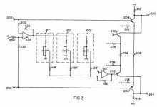
Feedbeside correction circuit for an amplifier USPat 4,132,958
Will elaborate on this
How is this one: Distortion reduction circuit for an inverting feedback amplifier, USPat 4,296,381 - the early realization of composite op amp?
p.s. Jan, could you please check your mail-box?
Feedbeside correction circuit for an amplifier USPat 4,132,958
Will elaborate on this
How is this one: Distortion reduction circuit for an inverting feedback amplifier, USPat 4,296,381 - the early realization of composite op amp?
p.s. Jan, could you please check your mail-box?
Jan,
Have seen several of such topologies. One remarkable was in E & WW some 10 years ago. It was 2 amps in series. One branch to handle the high power and one very fast low power branch to correct (subtract) the distortion products of the main power amp.
And can we consider the Quad 405 output topology also as “feed-beside”? If then their marketing department missed something.
Cheers 😉
I agree that is very much like feedforward. Somtimes you even see it inside IC opamps. I think Hofer called it Feedbeside either tongue-in-cheek or to give the patent more stature...
Jan Didden
Jan Didden
dimitri said:[snip]How is this one: Distortion reduction circuit for an inverting feedback amplifier, USPat 4,296,381 - the early realization of composite op amp?[snip]
No, this is in my view, conceptually, very much like the Hawksford error corrrection, but in this case applied to the amp input instead the output stage.
What it does is look at the voltage difference between V+ and V- with the loop closed. This will be a very small signal, in effect a fraction of the input signal of Gclosed loop/Gopen loop. It is often referred to as Error Voltage and in fact that is what it is: the voltage required to maintain the output voltage, and this error voltage is multiplied by the open loop gain. In an ideal opamp the error voltage would of course be zero.
(We often do not realise it, but we can add all the feedback we want, but the opamp itself remains in open loop mode!)
So what Hofer does is add that error voltage to the opamp input to compensate for it, much as Hawksford adds the difference between input and output of the output stage to the stage's input to compensate for it.
Neat, huh?
Jan Didden
To Jan : Jan, you are realy good theoreticaly thinking man, so I have for you this question : whatabout to use in differential input stage " supertransistors ", used in OPA 660 ( for example ), 'cos they have excellent transfer characteristic ?
JensRasmussen said:While on the topic of Current feedback opamps.
Can I model the opamp like this?
\Jens
Jens, why don't you model out the frequency dependent gain model of your "CFB" and a typical CFB and see if there is a difference.
It ought to be apparent to you that CFB isn't just a marketing thing after that excercise.
If you have trouble modeling it out, please let us know.
JensRasmussen said:And what was the name of your university again? Does it support this name?
And what was then name of the textbook you studied? Does it support this name?
And what was the name of your professor? Does he/she support this name?
And what is blueberry doing in the sky; I thought it Lucy was there?
🙂
\Jens
if we had relied on textbooks for truth, the earth would have been the center of universe, no man would be flying and telephony wouldn't have been possible, etc.
and I am sure whatever professors you had in college wouldn't be worth his / her name tag's worth if s/he couldn't recognize the inherent and real difference between a CFB and a VFB.
Majority cannot assure you the truth but you have to wonder why the majority doesn't agree with you.
The bandwith gain product thing (which some mentioned a while ago) is real and you will not be able to get a VFB to function like a CFB in that department.
If you could, you would have defied the known laws of physics (not that it is impossible).
Hello,
First of all the university / professor / textbook were intended as a joke, but something was obviously lost in translation – sorry about that.
Secondly I never disputed that CFB have properties that many applications can make good use of. I just don’t understand why names of definitions as old as 50 years have been bend to something unrecognisable during several threads and by many semiconductor manufactures. 🙄
I still claim that a good definition of a VFB circuit is a setup, where the feedback signal contains information about the output voltage of the system. This information can be transported as either a current or a voltage.
Furthermore I think that the only good definition of a CFB circuit is a setup where the feedback signal contains information about the outgoing current. Again the information can be transported as either a current or a voltage.
This is really what I think all this is about. Confusion over definitions.
The whole point of this is to say that I think the “new” definition of CFB as a system where the feedback signal is a current is rather misleading – simply because this would mean that any opamp with a differential input made by BJTs would be a CFB system, while the same topology using FETS would be VFB, simply because of a LOWER or HIGHER input impedance.
This makes it impossible to tell witch is what – and this may in fact be the whole point of the manufactures. Simply to create so much confusion that no one without datasheets and schematics can judge what topology is being used by what manufacturer. This thereby makes an already non transparent market even more difficult to understand for Jane and John consumer.
Regarding my model, I realise after a good night’s sleep and sonnya’s drawing that I was completely wrong. Of cause I need some sort of current to voltage converter on the inverting input, or else it’s just an asymmetrical opamp.
\Jens 🙂
- Status
- Not open for further replies.
- Home
- Amplifiers
- Solid State
- Current feedback - Voltage feedback, how do I see the difference?