Galileo 'proved' to himself, by noting the phases of Venus, that the earth went around the sun. Then he got into trouble for broadcasting it. The Earth was always considered round by learned individuals, since the ancient Greeks. Popular history always confuses this stuff.
janneman said:Shoot, I *promised* not to post here anymore. Ohh well...
😀 😀 😀
Since it shows up in many threads here that feedback by it self seems not defined at all, how can you discuss current feedback versus voltage feedback? Com’on guys …

But whatever you name it (or not name it) there is one remarkable difference: For a current feedback topology the open loop gain depends on the impedance of the feedback network. That’s why capacitors in the feedback path are not done then. In a voltage feedback topology open loop gain does not depend on feedback network impedance (in general).
Cheers 😉
Sorry Pjotr,
you have to be more accurate. Open loop gain NEVER depends on the feedback network....😉
Jan Didden
you have to be more accurate. Open loop gain NEVER depends on the feedback network....😉
Jan Didden
Pjotr said:[snip]Since it shows up in many threads here that feedback by it self seems not defined at all, how can you discuss current feedback versus voltage feedback? Com’on guys …
[snip]
You may remember that I offered to send Cherry's paper that gives an exhaustive discourse on all kinds of feedback to anyone asking. I had 2 (two) takers. So, if you don't see any definition of feedback here, it is because you (plurial) apparently have your eyes tightly shut. No offense meant...
Jan Didden
As for the basic question in this threads' title:
If you short the output, and the feedback signal goes to zero, that's voltage feedback.
If you disconnect the load, and the feedback signal goes to zero, you've got current feedback.
Is that classical definition not clear, clean, easy to understand and not up for interpretation?
When did we lose the capability to stick to this kind of simple definitions? Were it the marketeers, after all?
Jan Didden
Pjotr said:
........feedback by it self seems not defined at all, how can you discuss current feedback versus voltage feedback?
Pjotr....how could you say this in broad daylight...with the lights on...at midday...???
There are only FOUR possible types of electrical feedback...defined exhaustively here:
http://diyaudio.com/forums/showthread.php?postid=423522#post423522
Pjotr said:
For a current feedback topology the open loop gain depends on the impedance of the feedback network. .............
.......In a voltage feedback topology open loop gain does not depend on feedback network impedance (in general).....
No....for so-called 'current feedback', the feedback network's component values are deliberately chosen so that they constitute a significant load on the first stage......
This means that local first stage gain varies as you vary your feedback resistors......(Remember local gain of simple common emitter stage~Rc/Re???)
...This implies that for low closed loop gains with 'current feedback', the Thevenin resistance at the feedback summing node must necessarily increase, since the reduction in closed loop gain is facilitated by increasing the value of the grounded resistor in the feedback network....
This must therefore mean that local first stage gain is reduced....which must perforce be accompanied by a reduction in foward path gain.....
This then is the mechanism by which bandwidth appears constant over a defined range with reduced closed loop gain......
Now.....for so-called 'proper' voltage feedback, the feedback network is deliberately arranged so that its loading effect on the summing node is near nil....
Viz: varying component values in the feedback network DOES NOT vary LOCAL first stage gain...
...Hence foward path gain does not vary with feedback network component values over a vast range of resistor values.....
WHY?? BECAUSE the node at which subtraction takes place is buffered from the feedback network by an emitter follower...
This then is one of the most significant characteristics of the Differential pair.....
Now...does all this mean that the significant loading on the first stage by the feedback network constitutes 'current' feedback??
HELL NO!!!!!
So...what exactly is this new-fangled 'current' feedback???
Simple: Deeply compromised, (AKA crapulous...AKA excreble) voltage feedback....
Cheers.
Jan and Mike,
Seems you missed the
But what I’ve learnt decades ago on college is when the impedance of the input of the circuit where the feedback path is acting on is relative low (so there develops negligible voltage) we are calling it current feedback. On the other hand if that input impedance is relatively high (and drawing negligible current) we are calling it voltage feedback. This is the same op-amp makers are dealing with it, so why are audio amp makers wrong when they follow the same lines? It is just a naming convention.
B.t.w. Mike your 4 possibilities of configurations are not conflicting with that, isn’t it?
Cheers 😉
pjotr
read very carefully through the whole thread...please...
http://diyaudio.com/forums/showthread.php?postid=423582#post423582
🙂
read very carefully through the whole thread...please...
http://diyaudio.com/forums/showthread.php?postid=423582#post423582
🙂
I did Mike, as I did read other threads concerning this subject. But this whole thread is a lot about nit-picking conventions IMHO blurring the original question and making it completely not-understandable in the end.
There is a load of good app. notes on the internet, so what can we add to them?
Cheers 😉
There is a load of good app. notes on the internet, so what can we add to them?
Cheers 😉
Pjotr said:There is a load of good app. notes on the internet, so what can we add to them?
Cheers 😉
You can throw the majority on 'current' feedback in the bin....sharpish.

mikeks said:
You can throw the majority on 'current' feedback in the bin....sharpish.
Hmm ...
Once again we are submerged in semantics........
Someone commented the JLH 10W Class A used current feedback because the signal was injected back into the input transistor emitter, whose potential of course is controlled from the base.
Hmmm. To go back to Jan's definition, which is based on causation, not implementation, for current feedback, and in sharp contrast to voltage feedback, if there is no load connected, there should be no feedback.
What happens with the JLH?
Cheers,
Hugh
voltage / current mode endless debate
Folks, this VFB/CFB issue is getting old. Much of it revolves around semantics, and some "facts" presented here are off the mark.
First of all, I don't know of any circuit or device which can truly be called "voltage-mode" or "current-mode" in the purest sense. A VFB op-amp operates by forcing the high impedance inputs to be equal via servo (feedback) control action. How does this take place? Via *summing* action at the negative input terminal. What is the quantity being summed at this input in a *VFB* op-amp? It is *current*, not voltage. By virtue of the op-amp input terminal's high impedance, very little current flows into the op-amp, so that the input resistor current very nearly equals the feedback resistor current. Nonetheless, it is called a *voltage-feedback* (VFB) op-amp. Of course, the quantity fed back is the output voltage, and the output will drive the inverting input terminal voltage in order to match the noninverting terminal voltage. Hence, we can call it "VFB". But, the high input impedance makes this possible, by forcing the currents at the input to be equal. The input resistances of the input terminals must be larger than the resistors in the circuit, or the currents will not precisely sum. It is quite apparent (to me, anyway) that *BOTH* voltage and current are essential for proper operation. The term "VFB" could be considered a *misnomer*, couldn't it? In the strictest sense it is.
Likewise, a "current-feedback", or CFB op-amp relies on *BOTH* current and voltage to operate properly. The term "CFB" could rightly be called a misnomer. Frankly, any circuit labeled as "V" or "I" type can be considered a misnomer, if you wish to split hairs.
Regarding a BJT, a small but very vocal minority insists that Bell Labs, the IEEE, semiconductor fabricators, university professors, etc. have had it all wrong for 55 years when they regard the BJT as a CCCS (*current* controlled current source). This minority insist that a BJT is a VCCS (*voltage* controlled current source). Their reasoning is that a voltage, Vbe, from base to emitter is what "causes" base current, Ib, to flow. The problem with this argument is that the term "current controlled", as used by the majority, does not imply the *absence* of voltage. Voltage and current are mutually inclusive, or co-existant. You don't get one without the other. The term CCCS simply implies that the BJT output quantity, the emitter current, Ie, is an amplified facsimile of the base current Ib. The fact that Vbe is absolutely necessary is well understood and undisputed by the majority. By telling us that Ib could not exist without Vbe, they are merely overstating what is all too obvious. The Vbe waveform looks nothing like Ib, or Ic. The only way a BJT could function as a true VCVS, is to drive the base-emitter junction directly with a voltage source. The distortion would be horrendous. I've never seen a BJT driven in such a manner. The base and/or emitter resistors swamp the non-linear Ib/Vbe junction characteristic, so that the base current Ib, is a faithful facsimile of the input signal, and likewise for Ic. A BJT requires BOTH voltage and current at its input to operate, but Ic is MUCH more faithful to Ib than to Vbe, hence the term CCCS. Likewise, a MOSFET requires BOTH input current and voltage to operate. The gate charge or capacitance, requires current in order to effect a voltage change. MOSFETs are VCCS devices. Being voltage controlled only means that the drain current Id, is an amplified facsimile of Vgs. The gate current is absolutely necessary in order for the FET to work. But, the output quantity, Id, looks NOTHING like Ig, the gate current. That's why it is referred to as "voltage" controlled. Not too difficult, is it?
How about transformers? There are "voltage transformers", VT, and "current transformers", CT. The truth is that both VT and CT *transform* BOTH V and I. Hence both terms can be considered misnomers. The VT is placed across (in PARALLEL with) a low-impedance voltage source, whereas a CT is placed in SERIES with a source-load circuit. The VT is optimized to be terminaed with an impedance LARGER than the source impedance, and the CT gets terminated with a SMALLER impedance. Hence, the differing terms.
Also, a current-mode SMPS regulates voltage by sensing current. A voltage mode SMPS regulates voltage, but also senses current for short circuit protection. Also, the voltage mode SMPS behavior is greatly affected by the operating mode (continuous or discontinuous) of the inductor *current*.
It should be clear by now that there is no such thing (as far as I know) as a pure "V-mode" or "I-mode" circuit. The terms are used rather loosely. The op-amp producers had to give this new topolgy a different name, so they chose "CFB". Should we chastize them for a bad choice? If the answer is YES, then let's be consistent. My grocer advertises "white grapes" that are actually pale green. How far do we go with semantic purism?
Also, the four amp-feedback configurations presented thus far, series-input/parallel-output, parallel-input/parallel-output etc. have always been called "SIPO", "PIPO", etc. in my undergraduate studies. We never used the terms VFB or CFB. If removing the load does not change the feedback at the input it is PARALLEL output feedback (SIPO, PIPO). If removing the load causes the feedback at the input to go to zero, it is SERIES output feedback (SISO, PISO). Of course, nomenclature is arbitrary, and I don't claim that my terminolgy is the only way. As far as I'm concerned, both terms, VFB and CFB, are misnomers if you're splitting hairs. I choose to not split hairs. The op-amp producers' VFB and CFB nomenclatures work fine for me. Let's move forward. Best regards to all.
Re: voltage / current mode endless debate
There is much that is vastly incorrect here......but i am tired..... goodnight....
P.S: The word 'semantics' has now been hi jacked by those who now choose to use it as a blanket label for everything they either don't or refuse to understand........... 🙄
Heck...why should we bother calling a current source a current source....lets call it voltage source.....to avoid debating 'semantics'... 🙄
AKSA[/i] [B] Someone commented the JLH 10W Class A used current feedback because the signal was injected back into the input transistor emitter said:
But, the high input impedance makes this possible, by forcing the currents at the input to be equal. The input resistances of the input terminals must be larger than the resistors in the circuit, or the currents will not precisely sum. It is quite apparent (to me, anyway) that *BOTH* voltage and current are essential for proper operation. The term "VFB" could be considered a *misnomer*, couldn't it? In the strictest sense it is.
Claude Abraham said:
This minority insist that a BJT is a VCCS (*voltage* controlled current source). Their reasoning is that a voltage, Vbe, from base to emitter is what "causes" base current, Ib, to flow. The problem with this argument is that the term "current controlled", as used by the majority, does not imply the *absence* of voltage.
Also, the four amp-feedback configurations presented thus far, series-input/parallel-output, parallel-input/parallel-output etc. have always been called "SIPO", "PIPO", etc. in my undergraduate studies. We never used the terms VFB or CFB. If removing the load does not change the feedback at the input it is PARALLEL output feedback (SIPO, PIPO). If removing the load causes the feedback at the input to go to zero, it is SERIES output feedback (SISO, PISO). Of course, nomenclature is arbitrary, and I don't claim that my terminolgy is the only way. As far as I'm concerned, both terms, VFB and CFB, are misnomers if you're splitting hairs. .......
There is much that is vastly incorrect here......but i am tired..... goodnight....
P.S: The word 'semantics' has now been hi jacked by those who now choose to use it as a blanket label for everything they either don't or refuse to understand........... 🙄
Heck...why should we bother calling a current source a current source....lets call it voltage source.....to avoid debating 'semantics'... 🙄
Re: Re: voltage / current mode endless debate
that definition probably does not factor in what is being fed back?
🙂
I would in general agree with your argument but your argument does flip flop between "theory" and "reality". there is no pure current feedback amps in the real world as there is no VCCS in the real world. Your arguments are far better presented if you restrict yourself either to the theory or the reality.
BTW, I would like to see when / where IEEE defined BJTs as CCCS.
while I disagree with mikeks on pretty much all his points on current-fedback amps, I would agree wholeheartedly with him on this.
AKSA said:Hmmm. To go back to Jan's definition, which is based on causation, not implementation, for current feedback, and in sharp contrast to voltage feedback, if there is no load connected, there should be no feedback.
Cheers,
Hugh
that definition probably does not factor in what is being fed back?
🙂
Claude Abraham said:Folks, this VFB/CFB issue is getting old. Much of it revolves around semantics, and some "facts" presented here are off the mark.
I would in general agree with your argument but your argument does flip flop between "theory" and "reality". there is no pure current feedback amps in the real world as there is no VCCS in the real world. Your arguments are far better presented if you restrict yourself either to the theory or the reality.
BTW, I would like to see when / where IEEE defined BJTs as CCCS.
mikeks said:P.S: The word 'semantics' has now been hi jacked by those who now choose to use it as a blanket label for everything they either don't or refuse to understand........... 🙄
while I disagree with mikeks on pretty much all his points on current-fedback amps, I would agree wholeheartedly with him on this.
'semantics'...?!!??
Heck...why should we bother calling a current source a current source....lets call it voltage source.....and conversely.....to avoid debating 'semantics'... 🙄
Heck...why should we bother calling a current source a current source....lets call it voltage source.....and conversely.....to avoid debating 'semantics'... 🙄
Re: voltage / current mode endless debate
they don't have to be mutually inclusive, especially in theory. You can take a VFB amp or a CFB amp.
and I would go one step further: if you break out a typical VFB amp with BJT-input stage, using the small signal BJT model (current-controlled current source), you will actually have a current feedback amp: you can just compare a CCCS with a CFB and it should be fairly clear to you.
Again, I still think mikeks is wrong in his assertions but let's not get carried too far. there doesn't exist pure CFB or VFB amps in the real world. a BJT starts to mimic a VCCS when its gain is sufficiently large.
Claude Abraham said:Voltage and current are mutually inclusive, or co-existant.
they don't have to be mutually inclusive, especially in theory. You can take a VFB amp or a CFB amp.
and I would go one step further: if you break out a typical VFB amp with BJT-input stage, using the small signal BJT model (current-controlled current source), you will actually have a current feedback amp: you can just compare a CCCS with a CFB and it should be fairly clear to you.
Again, I still think mikeks is wrong in his assertions but let's not get carried too far. there doesn't exist pure CFB or VFB amps in the real world. a BJT starts to mimic a VCCS when its gain is sufficiently large.
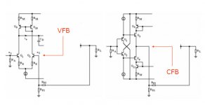
Save.Me:
All EE experts, please save me.
How should I call these?
A-feedback and B-feedback?
Alpha-feedback and Beta-feedback?
Base-feedback and Collector-feedback?
Male-feedback and Female-feedback?
White-feedback and Black-feedback?
Or...
I want to name these two, in a way or another.
All EE experts, please save me.
How should I call these?
A-feedback and B-feedback?
Alpha-feedback and Beta-feedback?
Base-feedback and Collector-feedback?
Male-feedback and Female-feedback?
White-feedback and Black-feedback?
Or...
I want to name these two, in a way or another.
Attachments
so ... what would you propose
We are talking about a particular topology of amplifier, whose interesting characteristic is that its loop bandwidth depends directly on the impedance of the feedback network seen by the inverting input. It has traditionally been called a "current feedback amplifier" because the error signal that is integrated on the compensation cap in the amplifier is directly proportional to the current in the inverting input.
So for those who object to the term "current feedback amplifier", what would you propose as a better concise and descriptive name for this topology?
BTW, in my opinion, all the semantic arguments are a waste of bandwidth.
mirlo
- Status
- Not open for further replies.
- Home
- Amplifiers
- Solid State
- Current feedback - Voltage feedback, how do I see the difference?