mikeks said:
True..at last YOU acknowledge that it IS INDEED voltage feedback...
That it is different from the stereotype voltage feedback applied to a diff. pair was never in dispute.

I have never disagreed that it fits the schematic that you call voltage feedback and as far as I can see the dispute has all the time been exactly whether there is a difference or not. If you could just learn to use complete senteces instead of posting single words or links or smileys, we migh have settled this dispute years ago.
This, however, does not make it 'special', or 'current feedback'.
Well, there is a difference. (Op) ampd usually referred to as voltage feedback output a voltage which i a function of the voltage difference between the inputs. In the ideal case this is a linear function. The ideal CFB (op) amp has a perfect unity gain buffer at the input and hence it is impossible to have a voltage difference between the inputs. It the output were a function of such a difference it would always output zero Volts, or some other constant voltage and be useless as an amplifier. Hence the theoretical CFB model must be given a special status as far as I can see.
As for the name, you already know I am not defending it, just using it.
Christer said:[snip]Well, there is a difference. (Op) ampd usually referred to as voltage feedback output a voltage which i a function of the voltage difference between the inputs. In the ideal case this is a linear function. The ideal CFB (op) amp has a perfect unity gain buffer at the input and hence it is impossible to have a voltage difference between the inputs. It the output were a function of such a difference it would always output zero Volts, or some other constant voltage and be useless as an amplifier. Hence the theoretical CFB model must be given a special status as far as I can see.[snip]
Exactly. Conceptually and practically, that "CFB opamp" is a CCII+: the input current (to the inverting input) is exactly conveyed to the current output, then voltage buffered to the final output.
In some cases it is much clearer to see: the MAX435/436 for instance, or the OPA860 I think it is.
The AD844 is something in between, in that the current output node is brought to the outside world but internally connected to the output buffer input. Most other "CFB opamps" are disguised as "opamps" although they really are buffered current conveyors.
So, there is a perfectly applicable name for such circuits, but, as the AD rep said, nobody buys them unless we call them opamps.

Jan Didden
janneman said:Exactly. Conceptually and practically, that "CFB opamp" is a CCII+:
the input current (to the inverting input) is exactly conveyed to the current output, then voltage buffered to the final output.
In some cases it is much clearer to see: the MAX435/436 for instance, or the OPA860 I think it is.
Or perhaps it is more than a CCII+. According to Scmids article
http://people.ee.ethz.ch/~hps/publications/2000cas.pdf
which jcx linked to earlier, the CFB opamp uses it as its input stage, but that is basically what you say. I don't know if his terminolgy is acknowledged or wide spread, but he identifies nine different types of op amps, where the CFB one is what he calls a H-V op amp.
So, there is a perfectly applicable name for such circuits, but, as the AD rep said, nobody buys them unless we call them opamps.
Well, they are mostly used in circuits where it is impossible to distinguish them from ordinary VFB op amps from just looking at the circuit, so in one way it makes sense. Maybe the problem is rather that the term op amp was long ago coined for a certain type of ideal amplifier, when other variations were not yet considered, so it would be better to use op amp as a broad term and then specify which particular subclass one means. But we would have a long way to go to get an established terminology, and the industry would continously mess it up for us along the road. 🙂
Christer said:
Well, there is a difference. (Op) ampd usually referred to as voltage feedback output a voltage which i a function of the voltage difference between the inputs. In the ideal case this is a linear function. The ideal CFB (op) amp has a perfect unity gain buffer at the input and hence it is impossible to have a voltage difference between the inputs.
With respect, Christer, your last sentance is completely untrue...
mikeks said:
With respect, Christer, your last sentance is completely untrue...
Could you elaborate on that? A perfect buffer has exactly gain 1, zero output impedance and infinite current capacity.
mikeks said:
Off topic:
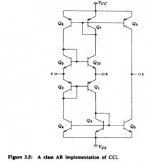
Mike, don't you think fig 3.5 is pure nonsense, because undefined bias? And positive bias point feedback?
I'm also interested to hear a good explanation. How is it then, enlighten us, MikeChrister said:Could you elaborate on that? A perfect buffer has exactly gain 1, zero output impedance and infinite current capacity.

Christer said:
Could you elaborate on that? A perfect buffer has exactly gain 1, zero output impedance and infinite current capacity.
Christer, the fundamental basis of 'CF' is a common-emitter transistor, in which stimulus is applied to the base, and voltage feedback applied to its emitter. Period.
Now, the only fundamental difference between this inferior construct and the traditional VF arrangement, is that the voltage fed back in the later is buffered from the emitter of this common emitter transistor by an emitter follower. Hence the emitter-coupled (or diff.) pair.
It does not get simpler than this.
Christer said:[snip]Well, they are mostly used in circuits where it is impossible to distinguish them from ordinary VFB op amps from just looking at the circuit, so in one way it makes sense. Maybe the problem is rather that the term op amp was long ago coined for a certain type of ideal amplifier, when other variations were not yet considered, so it would be better to use op amp as a broad term and then specify which particular subclass one means. But we would have a long way to go to get an established terminology, and the industry would continously mess it up for us along the road. 🙂
Yes indeed, I think the term opamp was initially used for a black box, if you will, an operational ciruit with infinite gain, infinite input impedance, zero output impedance etc. Reading historical tales from people like Bob Pease appear to indicate that that was the case. Early opamps were based on tube circuits.
You could have anything inside the box as long as the specs were met. Over the years we seem to have shifted to calling a particular contents of the black box, the high gain, diff input IC amplifier, as "the opamp".
Jan Didden
darkfenriz said:
Off topic:
Mike, don't you think fig 3.5 is pure nonsense, because undefined bias? And positive bias point feedback?
This circuit is obviously incomplete. Nevertheless, it demonstrates the point: No buffers a la Christer.
Attachments
darkfenriz said:
Off topic:
Mike, don't you think fig 3.5 is pure nonsense, because undefined bias? And positive bias point feedback?
... cannot find fig 3.5...?
Jan Didden
mikeks said:
Christer, the fundamental basis of 'CF' is a common-emitter transistor, in which stimulus is applied to the base, and voltage feedback applied to its emitter. Period.
So once again you are accusing me of being wrong by interpreting what I say based on your own definitions without telling it. How could one possibly have a serious and constructive discussion with you under such circumstances. You do exactly the same thing to others, which was the reason I entered this thread, asking the question you still haven't answered.
We are discussing the theoretical models here, not some wannabee theories slightly abstracted from real circuits. If you want to disagree with a definition, fine. Definitions are like axioms. They are not true or false, and you can make whatever definition you like. However, it somebody draws a conclusion from one set of definitions, you cannot claim that to be false just because the conclusion is not a valid one to draw from the definitions you prefer to use. That is elementary logic.
mikeks said:
This circuit is obviously incomplete. Nevertheless, it demonstrates the point: No buffers a la Christer.
Demonstrates what point? I have never made any claim about that circuit. It was you who linked to that paper.
mikeks said:
This circuit is obviously incomplete. Nevertheless, it demonstrates the point: No buffers a la Christer.
Mike,
How incomplete? I have a circuit like that working fine. Unless you mean there is no supply shown??🙄
Jan Didden
janneman said:
Mike,
How incomplete? I have a circuit like that working fine. Unless you mean there is no supply shown??🙄
Jan Didden
Of course it doesn't work. I just doesn't know it itself. 😉
janneman said:
Mike,
How incomplete? I have a circuit like that working fine. Unless you mean there is no supply shown??🙄
Jan Didden
No feedback network...compensation...etc
🙂
Christer said:
So once again you are accusing me of being wrong by interpreting what I say based on your own definitions without telling it. How could one possibly have a serious and constructive discussion with you under such circumstances. You do exactly the same thing to others, which was the reason I entered this thread, asking the question you still haven't answered.
We are discussing the theoretical models here, not some wannabee theories slightly abstracted from real circuits. If you want to disagree with a definition, fine. Definitions are like axioms. They are not true or false, and you can make whatever definition you like. However, it somebody draws a conclusion from one set of definitions, you cannot claim that to be false just because the conclusion is not a valid one to draw from the definitions you prefer to use. That is elementary logic.
What on earth are on about?

- Status
- Not open for further replies.
- Home
- Amplifiers
- Solid State
- Current feedback - not suitable for audio ?