Funny that you choose to quote the signature of somebody who agrees with me in all important aspects. 😉
However, you seem to either don't understand or have a very different interpretation of 'truth' than I have.
Bye, Mike.
However, you seem to either don't understand or have a very different interpretation of 'truth' than I have.
Bye, Mike.
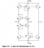
The inverting input of many (so-called) CFB amplifiers consists of the follower electrodes of a push-pull of complementary devices. This implies that the difference between the input voltage and the feedback voltage is treated in two different paths which have not strictly equal transconductances. To me, this is detrimental, at least, to the DC operating conditions of the whole amplifier.
Influenced by my knowledge of sophisticated inputs of amplifiers (Perrot’s patents, Cascomp, Self reference to Sziklai pairs as input devices), I wonder if the above push-pull could not be linearised by an additional circuit. I think of some kind of a linear VFB op-amp working with a gain of 1, its direct input being the new input of the whole amp, its inverting input being connected to the mid-point of the push-pull (the inverting input of the s-cCFB) and its output driving the push-pull through an adequate bias sdheme. The inverting input impedance should now be very low.
The main advantage of push-pull inverting input s-cCFB configuration is not generally yielded : it is fast because the subsequent VAS (a push-pull too) can deliver or absorb a lot of current, even in class B when needed. My idea, if it works - as some short experiences I draw seem to indicate - and does not induce other drawbacks, keeps intact this advantage and adds a good DC stability.
darkfenriz said:
I will ask again: what defines bias in following circuit?
I see only positive feedback, i.e. the higher questient current, the higher questient current.
That circuit does not look like any of the typical CFB/CCII+/H-V amp inputs stages that I have seen, so I am somewhat puzzled by it too. I also agree it seems to have a potential problem with thermal runaway, but so does certain other input circuits that seem to work in practice, like the Rush cascode that has been discussed quite a lot recently. If you see that circuit in an IC data sheet, it is most likely a simplified schematic and there tight transistor matching might perhaps help too. Personally, I would like to see some additions to the circuit to ensure a stable thermal behaviour. Some degeneration resistors might serve that purpose, perhaps.
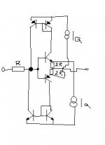
No, Christer, not thermally but electrically. It has just two mirrors against each other, so will either attenuate or magnify any questient current.
sorry for off topic once more
best regards
Adam
sorry for off topic once more
best regards
Adam
Christer said:[snip]If you see that circuit in an IC data sheet, it is most likely a simplified schematic and there tight transistor matching might perhaps help too. Personally, I would like to see some additions to the circuit to ensure a stable thermal behaviour. Some degeneration resistors might serve that purpose, perhaps.
It IS a simplified circuit. The actual circuit has lots of additional circuitry to set up the bias, and there is also emitter degeneration. But that's the silicon implementation, the thing can easily be used with only this circuit for the design.
You have to know though the bias currents in order to size the input/output currents for best linearity, of course.
Jan Didden
Christer said:.........somebody who agrees with me in all important aspects............
Really...?
http://www.diyaudio.com/forums/showthread.php?postid=422030#post422030
mikeks said:
Read post #143 in this thread instead of dragging up something that is 2 years old.
/Little mod hat on
I believe there is a persistency to continue a debate that ultimately will lead nowhere.
There is nothing wrong with disagreement but do keep the initial poster’s question in mind in this discussion.
/Little mod hat off
/Hugo 🙂
I believe there is a persistency to continue a debate that ultimately will lead nowhere.
There is nothing wrong with disagreement but do keep the initial poster’s question in mind in this discussion.
/Little mod hat off
/Hugo 🙂
janneman said:Most other "CFB opamps" are disguised as "opamps" although they really are buffered current conveyors.
Jan Didden
'Current conveyors' are really a development of so-called operational transconductance amplifiers, and have some similarity with 'CF' and VF amps in the sense that applying voltage stimulus to the non-inverting input causes a virtually equal voltage to appear at the inverting input in a closed loop arrangement.
Crucially, however, while the current appearing at the non-inverting input of an ideal current conveyor forces a virtually equal current to appear at the inverting input of a 'current conveyor', this is clearly not the case with so-called 'current feedback', op. transconductance or, indeed, generic voltage feedback arrangements.
Therefore, calling a 'CF' amp. a 'buffered current conveyor' is rather misleading.
Once again you surprise me! I've used CFB op-amps ever since the AD811 first came out, and the internal structure of this device, and just about all other CFB op-amps is indeed a CC-II with an output buffer feeding from the internal high-impedance node of the CC-II.
I strongly recommend reading the TI app-note SLVA051, which shows in detail the structural differences between VFB and CFB op-amps with a simple but rigorous mathematical analysis comparing between the two.
Ouroboros said:Once again you surprise me! I've used CFB op-amps ever since the AD811 first came out, and the internal structure of this device, and just about all other CFB op-amps is indeed a CC-II with an output buffer feeding from the internal high-impedance node of the CC-II.
janneman said:Indeed, Mike, it appears your understanding of a CCII+ is slightly off.
Jan Didden
Guys, you are absolutely right; i was refering to CC1. Apologies!
However, i fail to see how a 'CF' amp could be described as CC2, as with the later, feedback is returned to the 'X' node from the high impedance node...

Cheers.
Ouroboros said:I strongly recommend reading the TI app-note SLVA051, which shows in detail the structural differences between VFB and CFB op-amps with a simple but rigorous mathematical analysis comparing between the two.
Hi,
This ap. note starts by saying an CF op amp is a transimpedance op. amp.
Clearly this is wildly erroneous; algebraic relations developed using this assumption are equally incorrect. This is confirmed by Cherry:
http://www.diyaudio.com/forums/showthread.php?postid=949686#post949686
The mathematical analysis in the paper appears to be correct, in spite of the author stating (incorrectly) at the beginnning that the overall amp is a transimpedance amplifier, rather than just the output stage.
Mikeks, if you really believe the rest of the world has got it wrong, rather than just quoting a paper by Cherry (with no URL for us to download it from), you could give your own analysis.
I believe you are the same chap who produced the excellent pair of articles a few years ago in 'Electronics World' about SOA protection in power amplifiers, in which you showed that you could do the required mathematical analysis.
(If you are not the same person then Iapologise).
Ouroboros said:It is of course the output buffer of the CF op-amp that is the transimpedance amplifier.
On the contrary, a transimpedance amp. delivers a voltage output from a current input; this is not the case with this arrangement.
- Status
- Not open for further replies.
- Home
- Amplifiers
- Solid State
- Current feedback - not suitable for audio ?