I once asked Barrie Gilbert (ahum) why there were not more current conveyors like the AD844 and the (now obsolete) AD846 that had the Tz node brought out. That would make it so much more flexible!
His answer was that the few extra parasitic pF that the physical connection to an external pin causes would severely limit the hf performance.
(He also said that he had a much improved design of an AD844-type on the shelf but that it would stay there unless strong demand would materialise. I briefly thought about a one-million-members Group Buy but thought it less than realistic ;-)
Jan
Last edited:
The discussion is very dense. I recall that the proposals for the basic definition of feedback of amplifiers were interesting but not so easy to formulate.
I do not recall that a definition was proposed for current feedback. Did I miss it or was there not any ? Have you a link to dissipate my memory lapse ?
We’ve defined on numerous occasions current output and current feedback within the canonical amplifier topologies. There is no confusion about what they are and how they operate. If you are confused or cannot accept this, it is up to you to make the effort close your knowledge gap, or remedy your misunderstandings.
There is no confusion in my mind as to why VFA’s and CFA’s are different and operate on fundamentally different mechanisms at the topological level.
Trying to reason with you on these matters, with all due respect forr, seems pointless.
Last edited:
Hi Forr,We know it's the difference between CFA and VFA but the fundemental operation is still controlled by voltage.
Your message has been loud and clear over most part of this thread.
Why don't you simply stop, because by now we all know and respect your opinion.
No need to repeat it over and over.
Just a tip from Santa Claus

I once asked Barrie Gilbert (ahum) why there were not more current conveyors like the AD844 and the (now obsolete) AD846 that had the Tz node brought out. That would make it so much more flexible!
His answer was that the few extra parasitic pF that the physical connection to an external pin causes would severely limit the hf performance.
(He also said that he had a much improved design of an AD844-type on the shelf but that it would stay there unless strong demand would materialise. I briefly thought about a one-million-members Group Buy but thought it less than realistic ;-)
Jan
I may be open to correction, but a TAS is inherently very wide bandwidth, unlike a TIS (aka VAS) where the device Miller capacitance is problematical (requiring cascading or other techniques to overcome - which eats up output voltage swing). If you hang any capacitance off a TAS, you will bandwidth limit it. One of the ideal characteristics of a CFA is that the inherent OL bandwidths are very wide - if you are building an amplifier to deal with MHz signals, you clearly can have a BW limited gain stage.
SYN09 = SYN08?
Same city. Could be, syn08 stopped posting 2015, syn09 joined Dec 18.
There's also a syn23 though.
Jan
I may be open to correction, but a TAS is inherently very wide bandwidth, unlike a TIS (aka VAS) where the device Miller capacitance is problematical (requiring cascading or other techniques to overcome - which eats up output voltage swing). If you hang any capacitance off a TAS, you will bandwidth limit it. One of the ideal characteristics of a CFA is that the inherent OL bandwidths are very wide - if you are building an amplifier to deal with MHz signals, you clearly can have a BW limited gain stage.
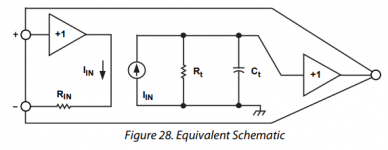
The extra pin parasitics would be in parallel with Ct, which is already about 4.5pF. Rt is about 3Meg.
Jan
Attachments
Last edited:
In CFA reducing THD at 1 MHz, means consequently THD at 1 kHz will decrease too?
By the same amount. Which raises the question if CFAs have any advantage in audio amplifiers. I would say no, but who am I to to open this can of worms 😀.
Welcome back!
I think ;-).
Time will tell.
I see your Linear Audio is no longer edited. Too bad, but not unexpected, I guess.
The extra pin parasitics would be in parallel with Ct, which is already about 4.5pF. Rt is about 3Meg.
Jan
As expected - at HF lead inductances of any external components would also create some nasty problems - you would have to be very careful IMV if you wanted to preserve HF performance. For audio really not an issue though.
In CFA reducing THD at 1 MHz, means consequently THD at 1 kHz will decrease too?
I think that depends also on how you do that 1MHz reduction. Just increasing the loop feedback should decrease it at all frequencies, but maybe there's another way that works different. What did you have in mind?
Jan
SYN09 = SYN08?
Yes, I got an error when I clicked the link that was supposed to update all of the SYN09 links to SYN08. May get resolved, may just be an oddity for the few posts affected.
Tony.
Time will tell.
OTOH, we can use each additional IQ point available here ;-)
I see your Linear Audio is no longer edited. Too bad, but not unexpected, I guess.
Yes. I got bored editing other people's writings ;-)
Jan
Welcome back!
My greatest achievements in the last 8 years is being on the cover of the "Queen Elizabeth Theatre Toronto Canada" King Crimson album 😀.
And some additions to my lab, which is now capable of every electrical measurement known to men, from 1uHz to 40GHz, and down to -140dB distortion and noise (the microscope is showing my age 🙂) But somehow I don't believe a 40GHz wideband audio amplifier would win the Absolute Sound prize, though.
The rest are details 😛.
Attachments
Ok, let's narrow the definitions and be careful how to name things. I won't make use of the name Middlebrook anymore, he used it for the General Feedback Theorem or GFT, for which I found this very interesting PDF. https://web.archive.org/web/20160331135833/http://ardem.com/downloads/GFTManual.pdfHere I must disagree. Middlebrook's test is designed to identify the current and voltage loop gains at specific points in any and all circuits, regardless of their names or topologies. It makes no attempt to identify circuit topologies, if that's what you mean by CFAs vs. VFAs. We can infer topologies from test results, but as I have identified, we do so at great risk.
But contrary to your belief, to my opinion he used the voltage and current injection technique right before the input and not just anywhere in the circuit. I will use the name "DIT" to identify the Dominant feedback mechanism" or DFM for short and not use it to prove whether you have to do with a CFA or a VFA. But it certainly can be used as a useful first indicator.
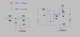
Look at your own construction in the image below with a current source in the feedback loop. I see no use at all for such a construction, but under strict conditions it came out as having current as DFM. However cutting the loop at the other end made the DFM look as voltage. But both cases are telling nothing about the topology.
Same situation you created with a VFA where a a low ohmic resistor R was inserted in front of the negative input, staying right there after the loop was opened for DIT. The DIT will now tell the DFM to be current. Again rather pointless. When the cut was made for inserting DIT between the junction of R-Rf and the negative input instead, DIT would have identified this circuit as having voltage as the DFM.
So with this, I think I can answer your questions at the end: Does a test exist which can demonstrate the predominant form of feedback at any point within a closed loop circuit? I think we can both say yes I think with the two examples above I have to say no. The outcome differs completely depending on where you make the cut.
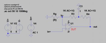
Second question: Does a test exist which can determine the topology (CFA vs. VFA) of the "gain block" (open loop amplifier) when mated with some sort of "standard" feedback network? I'm willing to be convinced, but I think it would be possible to weasel a way around it. To this question I can answer with a warm yes, by using the test created by me, giving a high probability. See image below.
Third question: Does a test exist which can determine the topology of the "gain block" when mated with an arbitrary feedback network? This I doubt. Thoughts? I have my doubts also, see earlier comment above.
Hans
Attachments
Last edited:
My greatest achievements in the last 8 years is being on the cover of the "Queen Elizabeth Theatre Toronto Canada" King Crimson album 😀.
And some additions to my lab, which is now capable of every electrical measurement known to men, from 1uHz to 40GHz, and down to -140dB distortion and noise (the microscope is showing my age 🙂) But somehow I don't believe a 40GHz wideband audio amplifier would win the Absolute Sound prize, though.
The rest are details 😛.
Wow - some good stuff in there. You and RJM must run pretty close for range of equipment.
I know SY has an AP - I saw it on YouTube.
Are you still using your Pretty Good Amplifier?
Last edited:
- Home
- Amplifiers
- Solid State
- Current Feedback Amplifiers, not only a semantic problem?