Cpaul, the arrows in your diagram seem to go in opposite direction which may give a false impression. Put vertically, they will go in the same direction.
I am not obligated to contest your most recent post to support the claims of post 837. It is certainly possible to explain this circuit in more ways than one. (But I will note that your explanation is far more complex than post 837's.)
However, by continuously claiming that CFA's don't employ current feedback, you are obligated to falsify post 837. I freely give you the right to change the direction of a current arrow if you'd like. That has absolutely no effect on the post's claims. If you wish to maintain that no current feedback occurs, you must find some flaw in post 837 other than the direction of a current arrow.
I will note that you have claimed that a CFA's feedback is not the difference of two currents; I have demonstrated that it is. You have yet to reply to this.
You have stated that the relative directions of input and output stage currents in a CFA denies the possibility of current feedback; I have pointed out that one set of directions must be associated with positive feedback and the other with negative. You have yet to reply to this.
Since we agree that voltage and current go hand in hand, it should come as no surprise that the existence of a voltage-centric explanation does not preclude the existence of a current-centric one. Please justify your claim that the latter is invalid, or renounce it.
What we are now calling a CFA is just an older design that skimped on the negative side of the input diff-amp, which means the feedback network has to be low-Z.
Some are confusing it with amps that use a small resistor or transformer in the output to sense output current, in order to create a well defined output impedance. These are not the same thing.
Originally, chip makers sold CFA amps that were a bit faster than a full diff-amp for RF and broadband applications. We can speculate at length why this configuration might be useful in audio applications.
What we are now calling a CFA is just an older design that skimped on the negative side of the input diff-amp, which means the feedback network has to be low-Z.
Not really. The feedback current into the inverting input is really minuscule and doesn't require a low impedance feedback network because of that.
The reason for the low impedance feedback R has to do with stability of the circuit. In fact, that resistor value is routinely used to tune the bandwidth of the circuit. See any CFA opamp data sheet.
Jan
Even if it seems more complex than yours, my circuit is nevertheless a practical version of yours. Just more detailed and based on very basic knowledge, it also makes clear that the inverting input is of low impedance.I am not obligated to contest your most recent post to support the claims of post 837. It is certainly possible to explain this circuit in more ways than one. (But I will note that your explanation is far more complex than post 837's.)
(by the way, your arrows on your circuit are in the right direction but graphically they look as not).
Plain agreement, I expressed the same idea in post 733 :I have pointed out that one set of directions must be associated with positive feedback and the other with negative.
The current coming from the amp output has the effect to decrease the current coming from the input stage, with a flavour of bootstrap analysed and not refuted post #698.
The fundamental role of the voltage controlled current source of the input stage prevents me to think otherwise.Since we agree that voltage and current go hand in hand, it should come as no surprise that the existence of a voltage-centric explanation does not preclude the existence of a current-centric one. Please justify your claim that the latter is invalid, or renounce it.
Try this... anyone .... might help you more....
what happens and why when you place a Cf across the Rf -- in a CMA? Compared to VMA?
(CFB vs VFB if you prefer).
THx-RNMarsh
Even if it seems more complex than yours, my circuit is nevertheless a practical version of yours.
Are we even looking at the same circuit? The Post 837 circuit is right out of CFA datasheets!
This interpretation of your statement was not obvious to me, so I'm glad we agree.(by the way, your arrows on your circuit are in the right direction but graphically they look as not).
Plain agreement, I expressed the same idea in post 733 :
The fundamental role of the voltage controlled current source of the input stage prevents me to think otherwise.
You are of course free to think as you like, but you certainly have presented no reason for doing so. The burden is on you to prove that more than one valid means of describing something is impossible.
Let's repeat a fact that you have not refuted:
1. CFA input stage current is equal to the ground current minus the current flowing between the output stage and the rest of the circuit; input stage current is the difference between these two circuit currents.
Analogously, VFA input stage current is the product of transconductances times the difference between two circuit voltages. If this implies that a VFA employs voltage feedback, there is no reason that the CFA current difference cannot imply current feedback.
We've seen that post #829.You are of course free to think as you like, but you certainly have presented no reason for doing so. The burden is on you to prove that more than one valid means of describing something is impossible.
Let's repeat a fact that you have not refuted:
1. CFA input stage current is equal to the ground current minus the current flowing between the output stage and the rest of the circuit; input stage current is the difference between these two circuit currents.
Both input stages of VFA and CFA deliver current under the control of transductance.Analogously, VFA input stage current is the product of transconductances times the difference between two circuit voltages.
Feedback is related to a function inside a servo-system. A servo-system has an input receiving a reference signal (or command) and has a controlled device at the output which gives a value with a strict correspondance with the input reference.If this implies that a VFA employs voltage feedback, there is no reason that the CFA current difference cannot imply current feedback.
The core of the system is the error detector and how the feedback value is built from the output. The value at the feedback input of the error detector has to be of the same nature as the value of the reference
The amplifiers we are looking at are very basic servo-systems because the natures of the input command and of the output result are the same : voltage.
The strict correspondance is under the control of feedback. The error detector is a voltage differential stage which can be a simple active device or a more sophisticated circuit. The error detector, receiving voltage at its input, needs a voltage at its input receiving feedback.
Finally I wonder if the expression CFA applies only to how the voltage at in- is built and not to the way the error detector works. If it is the case, CFA is only a semantic problem.
We've seen that post #829.
It is not clear at all that your reply applied to more than the "loadless" CFA.
May I also remind you of the "burden" that you did not respond to in that quote? Please see below, last four paragraphs.
Both input stages of VFA and CFA deliver current under the control of transductance.
That's just about as relevant to the discussion as being able to describe the VFA input stage currents as being related by a factor of transistor beta to the feedback network current, and therefore, the VFA employs current feedback.
Feedback is related to a function inside a servo-system. A servo-system has an input receiving a reference signal (or command) and has a controlled device at the output which gives a value with a strict correspondance with the input reference.
The core of the system is the error detector and how the feedback value is built from the output. The value at the feedback input of the error detector has to be of the same nature as the value of the reference
The amplifiers we are looking at are very basic servo-systems because the natures of the input command and of the output result are the same : voltage.
The strict correspondance is under the control of feedback. The error detector is a voltage differential stage which can be a simple active device or a more sophisticated circuit. The error detector, receiving voltage at its input, needs a voltage at its input receiving feedback.
Finally I wonder if the expression CFA applies only to how the voltage at in- is built and not to the way the error detector works. If it is the case, CFA is only a semantic problem.
Forgive me, but again, we get verbose irrelevancies which evade. You don't need an error amplifier of the type you describe to have a feedback loop. Consider a grounded gate MOSFET whose Source is driven by a current source which is part of a closed loop.
I say again what you have not refuted:
Your circuit is in no way more practical than the Post 837 circuit I presented, which can be found in almost any commercially available CFA datasheet. My explanation of its operation is noticeably simpler than yours.
The burden is on you to prove that more than one valid means of describing something is impossible.
A VFA input stage current is controlled by the difference of two voltages, one of which is some fraction of the output stage voltage. For these reasons, we call this voltage feedback.
A CFA input stage current is not just controlled by, but actually is the difference of two currents, one of which is not just some fraction of, but is the entire, current into/out of the output stage. For logically analogous reasons, which are made even stronger because the input stage current is not merely "controlled by", but "is", we call this current feedback.
Last edited:
...The value at the feedback input of the error detector has to be of the same nature as the value of the reference...
...The error detector, receiving voltage at its input, needs a voltage at its input receiving feedback...
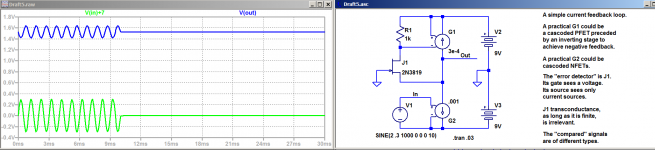
Not to detract from the points I raised in Post 848, to which I still request a reply, but attached please find a circuit which falsifies the quoted claim above.
Attachments
Datasheet copy each other. The op-amp is not specified CFA and there is nothing to expose the principle of the inside topology.Your circuit is in no way more practical than the Post 837 circuit I presented, which can be found in almost any commercially available CFA datasheet. My explanation of its operation is noticeably simpler than yours.
My circuit can be understood and analyzed by anybody having the basic knowledge in bipolar transistors. Voltage and currents can be checked, it is not a conceptual diagram. I note that there was no refutation of the circtuit and my comments about it.
Let me say that I am not in competition.
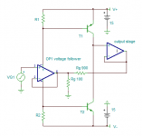
I propose a third circuit dating from before the CF era and on which the CFA principle is clearer than the two previous ones.
OP1 was one the first largely available integrated op-amp. Not long after the publication of this circuit, a demand emerged for integrated op-amp with independant power supply pins for the push-pull output transistors.
For sure, some engineers and manufacturers have been inspired by this circuit to think of a whole new family of circuits.
More to come.
Attachments
Last edited:
Don't you recognize the general structure of a CFA? I guess not. The attached substitutes the block diagram with a model of commercial CFA. Two different feedback network structures, same result. Current feedback explains both; your explanation needs to also. Note that R9's resistance is in series with the input stage transresistance, effectively significantly increasing it with no discernible effect on low frequency operation.Datasheet copy each other. The op-amp is not specified CFA and there is nothing to expose the principle of the inside topology.
I have no desire to discuss your explanation; my goal is to convince you that CFAs employ current feedback. Just because your explanation might be valid does not imply it is the only such.My circuit can be understood and analyzed by anybody having the basic knowledge in bipolar transistors. Voltage and currents can be checked, it is not a conceptual diagram. I note that there was no refutation of the circtuit and my comments about it.
Hmmm....From post 844: Even if it seems more complex than yours, my circuit is nevertheless a practical version of yours.
From post 850: Let me say that I am not in competition.
I propose a third circuit dating from before the CF era and on which the CFA principle is clearer than the two previous ones...
You are bringing up new issues and avoiding facing my claims and refutations of yours.
Here is a recap of some claims we've made, objections to yours I've offered, and subsequent abandonment of these matters by you without response:
1. The claim that "your" circuit is more practical.
2.
When challenged, there was no explanation offered of "the fundamental role" to justify your thought.The fundamental role of the voltage controlled current source of the input stage prevents me to think otherwise.
3.
Demonstrably false. See the circuit in post 849....The value at the feedback input of the error detector has to be of the same nature as the value of the reference...
...The error detector, receiving voltage at its input, needs a voltage at its input receiving feedback...
4.
Again, no response.A VFA input stage current is controlled by the difference of two voltages, one of which is some fraction of the output stage voltage. For these reasons, we call this voltage feedback.
A CFA input stage current is not just controlled by, but actually is the difference of two currents, one of which is not just some fraction of, but is the entire, current into/out of the output stage. For logically analogous reasons, which are made even stronger because the input stage current is not merely "controlled by", but "is", we call this current feedback.
I choose a simple circuit which manifestly belongs to the family of today's called CFAs and compare your analysis to mine. We agreed on some points, it is not bad.I have no desire to discuss your explanation; my goal is to convince you that CFAs employ current feedback. Just because your explanation might be valid does not imply it is the only such.
Fundamental role = regulation of the whole amplifying circuit.there was no explanation offered of "the fundamental role" to justify your thought.
Then in similar conditions a CFA input should have less distortion (at low frequencies). CFA is not recognised for that despite being able to be good in this domain. From where does come the distortion of the input stage ?A CFA input stage current is not just controlled by, but actually is the difference of two currents, one of which is not just some fraction of, but is the entire, current into/out of the output stage. For logically analogous reasons, which are made even stronger because the input stage current is not merely "controlled by", but "is", we call this current feedback.
The feedback current has to pass through base-emitter junctions at in-. Due to Rf current arriving at the node with Rg ,the impedance of the feedback network seen by the in- emitters is higher than what the resistors values suggest. It's a bootstrap effect we've already met.
I have to investigate a bit more in this direction because you consider in- as a current input, which implicates that the in- transistors operate in common base mode as Jan Didden suggested some days ago. I am a bit suspicious here.
Voltage feedback vs Current feedback
https://www.ieee.li/pdf/viewgraphs/current_feedback_vs_voltage_feedback_amplifiers.pdf
-RNM
https://www.ieee.li/pdf/viewgraphs/current_feedback_vs_voltage_feedback_amplifiers.pdf
-RNM
Although you can use the standard voltage divider equations to calculate the voltage at the feedback summing node where Rg and Rf meet, in a correctly working CFA you still have a further current supplied into this node from the emitter of the buffer transistor (and therefore the same current in its collector - we can ignore base bias currents for this basic analysis) such that the voltage at the emitter of the DB transistor equals the non-inverting input voltage. The only way to understand CFA operation in this context is to therefore consider its inverting input operation in current mode terms.
At DC and LF, even at near full output, the change in DB transistor collector current to balance the summing junction node current from Rf is tiny - in a practical amplifier (70 dB open loop gain at DC) single digit uA assuming a 2k DB collector load resistor. As frequency increases, the balancing current increases dramatically so that at a few MHz, it can be as much as 3 orders of magnitude higher (as a result in the drop of the compensation capacitance Xc). You can test this by feeding a fast rise time square wave into the CFA - the collector current will peak at 5-8x the standing current.
At DC and LF, even at near full output, the change in DB transistor collector current to balance the summing junction node current from Rf is tiny - in a practical amplifier (70 dB open loop gain at DC) single digit uA assuming a 2k DB collector load resistor. As frequency increases, the balancing current increases dramatically so that at a few MHz, it can be as much as 3 orders of magnitude higher (as a result in the drop of the compensation capacitance Xc). You can test this by feeding a fast rise time square wave into the CFA - the collector current will peak at 5-8x the standing current.
Bonsai, this is a nice analysis. Can I extend it a bit? Let's start with the open loop situation, where we have an emitter resistor Re to ground at the inv input. Then the input signal causes a collector current to drive the output stage, and this current also appears in Re.
Now we close the loop with Rf. What direction does the current in Rf flow, i.e. does IRf add to IRe or subtract from IRe? I believe it depends on the required feedback action, i.e. if the output voltage is too high, IRf will subtract from IRe so as to lower Vout; if Vout is too low, IRf will add to IRe so as to raise Vout.
That means that the 'direction' of IRf has nothing to do with the discussion whether it is current feedback or not.
Nevertheless, I expect the feedback to be degenerative so under normal circumstances Vout is lowered by the feedback thus IRf subtracting from IRe.
Agreed?
Jan
Jan, thank you. My explanation was done using voltages in part because forr seems more comfortable using this approach. But, a CFA is still a CFA however you cut it and fundamental operation is about the current injected into the inverting input
Let the summing junction where Rf, Rg and Re join be called Vsum (this is the inverting input). Assume that Vi = the voltage at the emitter of the diamond buffer (DB) output transistor and we call this Vi', so Vi = Vi' (this is indeed the case in a conventional 4 transistor DB where the Vbe's cancel) .
(Vi'-Vsum)/Re is the current you see in the collector of the DB output transistor. So, the currents add into Rg in accordance with the signal polarity to maintain Vi' = Vi. The higher Vi, the more current is suppled into Rg from Rf and Re - this is negative feedback - no positive feedback involved.
You can do this exact same analysis with currents and resistors and you still end up with the same intuitive explanation of operation.
When I visualize this, I to keep the output stage quiescent current (Iq) separate from the signal current in this analysis. Iq sets the bias up for the second stage (I have settled on 1mA in my designs). As mentioned earlier, the signal current at DC and LF is very low and this of course is added(subtracted) from Iq depending upon the signal polarity.
Separately, you can see straight away that there is a quite narrow range of values for Rf, Rg and Re required for correct operation. If Rg and Rf are set too high (lets say similar to the kind of values you might find in a VFA), then the output current Iq will be too small and the second stage wont work properly. If the values are set too low, you run into other problems like saturation.

A VFA input stage current is controlled by the difference of two voltages, one of which is some fraction of the output stage voltage. For these reasons, we call this voltage feedback.
As the transistor emitter current of a CFA is controlled by the difference of two voltages (Vbe), we can say that a CFA input stage is controlled by the same way as a VFA.
A CFA input stage current is not just controlled by, but actually is the difference of two currents, one of which is not just some fraction of, but is the entire, current into/out of the output stage. For logically analogous reasons, which are made even stronger because the input stage current is not merely "controlled by", but "is", we call this current feedback.
As all these currents are controlled by the voltage difference between base and emitter of the input transistor(s) we can also call it voltage feedback.
The current in one branch of a differential is the difference between the total long tail current and the other branch, I don't think you can say that the current in one branch of a differential is "current controlled".
As the transistor emitter current of a CFA is controlled by the difference of two voltages (Vbe), we can say that a CFA input stage is controlled by the same way as a VFA.
As all these currents are controlled by the voltage difference between base and emitter of the input transistor(s) we can also call it voltage feedback.
The current in one branch of a differential is the difference between the total long tail current and the other branch, I don't think you can say that the current in one branch of a differential is "current controlled".
I must disagree. Please see my next post to forr.
"As all these currents are controlled by the voltage difference between base and emitter of the input transistor(s) we can also call it voltage feedback.
The current in one branch of a differential is the difference between the total long tail current and the other branch, I don't think you can say that the current in one branch of a differential is "current controlled".
This is not correct. In a standard DB, the input and buffer transistor Vbe's cancel so that Vi+ and Vi- are equal when operating in the linear mode. Vbe does not enter into the equation (even if you remove Re and just rely on the internal emitter resistance re') And, in a 'single ended CFA' the Vbe does not materially affect the fundamental operation in which a current (+ or -) is injected into the inverting input (IMPORTANT: this is where Rf, Rg and Re all meet) in order to balance the summing junction currents.
- Home
- Amplifiers
- Solid State
- Current Feedback Amplifiers, not only a semantic problem?