DIT Oh!
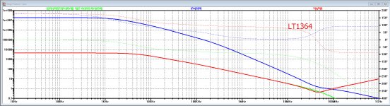
If you apply the DIT rule to the LT1364 it must be a CFA because it uses a 500 ohm resistor to drive the inverting input.
The ratio of R to 1/gm of the input stage is something like 500:25 range (since the opamp draws only 4 mA so likely each buffer is biased at 1mA so 1/gm is around 25 ohms). This ratio is well into the CFA range by the DIT test. The datasheet calls it a VFA, so if the DIT rule is to be used by the industry they will need to change the naming (and redo a few datasheets).
The ratio of Rf//Rg to 1/gm of the input stage is what tips from CFA to VFA. When Rf is removed we can vary Rg from small value and you have a VFA up to a large Rg and you have a CFA using the Middlebrook/Franco DITrule. In this case with no Rf the transition from VFA to CFA is with NO global feedback. Oh!
So is the DIT method still valid with no Rf? If it is valid then where is the feedback? It must be emitter degeneration of the input stage. Then we must conclude the "F" in CFA and VFA is referring to the input stage local feedback and not the global feedback that we all seem to be discussing.
I think this might be the key to the semantics question. After all, emitter degeneration is current feedback by the classical definition where current of the input stage is sensed by a series resistor and the information is feedback as a voltage (since we have a voltage controlled device we have to convert current to voltage to use it).
So the DIT rule is really only telling us how much degeneration feedback we are using for the input stage.
As forr pointed out in Post 1307 and CPaul echoed (quoted above) under the DIT rule "the CFA name does not refer anymore to a topology but to a relation between two impedances."
So where does this leave us (as audio amp designers) in this discussion? Do we accept the DIT rule or not for the naming of amplifiers? Has the DIT rule appeared in the IEEE etc literature and if so is it accepted now or not by the IC industry?
Cheers,
IH
When it comes to modern double diamond pairs biased by current sources and interconnected by a resistor between their emitters, I would have to say that by the above rule, these are enhanced VFAs.
If you apply the DIT rule to the LT1364 it must be a CFA because it uses a 500 ohm resistor to drive the inverting input.
The ratio of R to 1/gm of the input stage is something like 500:25 range (since the opamp draws only 4 mA so likely each buffer is biased at 1mA so 1/gm is around 25 ohms). This ratio is well into the CFA range by the DIT test. The datasheet calls it a VFA, so if the DIT rule is to be used by the industry they will need to change the naming (and redo a few datasheets).
There is another thing to consider with the DIT rule: what happens if you make Rf very large?Your proposal has the advantage of being backed up by something we can measure. At the very least, even without the order of magnitude qualification, this is a way to determine whether voltage or current feedback predominates at the inverting input of any amplifier. (Note that while the total loop gain is the same everywhere in a given circuit, the balance between current and voltage loop gains varies depending on the point in the circuit that the measurement is being made.)
However, this does not allow us to distinguish between topologies. CFA manufacturers' recommended feedback network component values for certain gains actually lead to cases where voltage feedback predominates. And even if this didn't happen, it would still be possible to achieve VF by using suitably low-valued components. So then I could change "topologies" by simply changing a component value. I don't find this very satisfying.
My personal preference for discriminating between topologies is to ask a simple question: what is the source of the signal current in the amplifier input stage? If it is a current source which is part of the input stage, then we have a VFA; if it is the feedback network, it's a CFA.
The ratio of Rf//Rg to 1/gm of the input stage is what tips from CFA to VFA. When Rf is removed we can vary Rg from small value and you have a VFA up to a large Rg and you have a CFA using the Middlebrook/Franco DITrule. In this case with no Rf the transition from VFA to CFA is with NO global feedback. Oh!
So is the DIT method still valid with no Rf? If it is valid then where is the feedback? It must be emitter degeneration of the input stage. Then we must conclude the "F" in CFA and VFA is referring to the input stage local feedback and not the global feedback that we all seem to be discussing.
I think this might be the key to the semantics question. After all, emitter degeneration is current feedback by the classical definition where current of the input stage is sensed by a series resistor and the information is feedback as a voltage (since we have a voltage controlled device we have to convert current to voltage to use it).
So the DIT rule is really only telling us how much degeneration feedback we are using for the input stage.
As forr pointed out in Post 1307 and CPaul echoed (quoted above) under the DIT rule "the CFA name does not refer anymore to a topology but to a relation between two impedances."
So where does this leave us (as audio amp designers) in this discussion? Do we accept the DIT rule or not for the naming of amplifiers? Has the DIT rule appeared in the IEEE etc literature and if so is it accepted now or not by the IC industry?
Cheers,
IH
Attachments
Last edited:
I welcome your contributions to this matter.
My comments were limited to using Middlebrook alone to distinguish between CFAs and VFAs. Not sufficient in my opinion for the reasons I've given.
Slew on demand by definition is a large signal behavior and can have nothing to do with Middlebrook which is solely a small signal analysis.
In the model I have made available based upon the Middlebrook DIT, you can freely change the values of the feedback network and see whether it is still meeting any of the conditions.Your proposal has the advantage of being backed up by something we can measure. At the very least, even without the order of magnitude qualification, this is a way to determine whether voltage or current feedback predominates at the inverting input of any amplifier. (Note that while the total loop gain is the same everywhere in a given circuit, the balance between current and voltage loop gains varies depending on the point in the circuit that the measurement is being made.)
However, this does not allow us to distinguish between topologies. CFA manufacturers' recommended feedback network component values for certain gains actually lead to cases where voltage feedback predominates. And even if this didn't happen, it would still be possible to achieve VF by using suitably low-valued components. So then I could change "topologies" by simply changing a component value. I don't find this very satisfying.
With very low values, the CFA might no longer be classified as a CFA, however stability does not allow to make the values too low. But you can test your circuit exactly as it is going to be used.
You can do that when you know what's inside. But yes, it's another way of looking at it.My personal preference for discriminating between topologies is to ask a simple question: what is the source of the signal current in the amplifier input stage? If it is a current source which is part of the input stage, then we have a VFA; if it is the feedback network, it's a CFA.
I think that cannot be any doubt about that.When it comes to modern double diamond pairs biased by current sources and interconnected by a resistor between their emitters, I would have to say that by the above rule, these are enhanced VFAs.
Hans
Doesn't the double diamond VFA just have this same slewing on demand feature ?One more thing to consider: The CFA topology enjoys "slewing current on demand" even when Middlebrook says that voltage feedback predominates. Middlebrook alone is not a good criterion for distinguishing between a CFA and a VFA.
Hans
I'm sure you're not trying very hard.
Correct. But I experienced many times in hifi fora.
... and a voltage, unless your load and sense resistors are dead shorts.
Of course, but the feedback controls current in the sense. VCCS or CCCS
Another interesting question. I'd have to see the circuit. First, how would you bias your emitter follower? If with a constant current source, then on a voltage stroke in one direction, the original input stage would benefit from the "slewing current on demand" feature of the CFA. But in the other direction, it would have the VFA characteristic of being limited by the current source current. This is not a circuit I'd seriously consider using. Perhaps you'd care to propose something useful for discussion?
Still, dwelling on your question, since both the original input stage and the modified new one would presumably see a feedback network whose impedance is very much lower than their own, Middlebrook would say that voltage feedback predominates in this circuit.
Sorry, I would have said where I put the emitter follower : at the ouptut of the input stage
I would say that the circuit topology is CFA. Certainly, it retains the CFA feature of "slewing current on demand". However, I don't believe it would have the "constant bandwidth" feature of the CFA as you lowered the value of R8. So it's kind of a combination of the two, I'd guess. Again, I'd question the usefulness of a circuit like this.
"current on demand" is not a exclusive feature of CFA.
I have not the same opinion on the circuit which I could test a version, alone or as the output stage of a nested feedback amp.
If you apply the DIT rule to the LT1364 it must be a CFA because it uses a 500 ohm resistor to drive the inverting input.
Where in the circuit would you propose to apply DIT? It makes a difference. Normally, this would be done at the inverting input. There, you'd find a VFA, not a CFA.
There is another thing to consider with the DIT rule: what happens if you make Rf very large?
The ratio of Rf//Rg to 1/gm of the input stage is what tips from CFA to VFA.
To be precise, what it tips is the predominant form of feedback in the circuit.
When Rf is removed we can vary Rg from small value and you have a VFA up to a large Rg and you have a CFA using the Middlebrook/Franco DITrule. In this case with no Rf the transition from VFA to CFA is with NO global feedback. Oh!
So is the DIT method still valid with no Rf?
In the referenced article, DIT applies only when there is a global loop. You can't have a return from a forward signal without one.
As forr pointed out in Post 1307 and CPaul echoed (quoted above) under the DIT rule "the CFA name does not refer anymore to a topology but to a relation between two impedances.
Ummm, no I definitely did NOT echo that. The impedance relationship determines the predominant form of feedback, not the name of the circuit, and not its topology.
So where does this leave us in this discussion? Do we accept the DIT rule or not for the naming of amplifiers?
I would say no.
(1) It does not speak to circuit topology.
(2) If I connect a 100 ohm resistor between the inverting and non-inverting inputs of a 741 op amp, connect a voltage source to the non-inverting input, and apply a feedback network of 10k impedance, DIT will tell you you have predominantly current feedback.
(3) DIT is silent on the question of whether or not a circuit has the CFA-like characteristics of slewing current on demand.
Has the DIT rule appeared in the IEEE etc literature and if so is it accepted now or not by the IC industry?
Cheers,
IH
I very much doubt it, but I can't prove the negative.
Slew on demand by definition is a large signal behavior and can have nothing to do with Middlebrook which is solely a small signal analysis.
True. You assume I think otherwise?
Doesn't the double diamond VFA just have this same slewing on demand feature ?
Hans
Yes. How does that relate to the statement you quoted?
Herve,Hans,
my emitter follower is located at the output of the input stage, so that the output current of the input stage is not the current coming from the output stage.
Here is the DIT of your design.
It is definitely a CFA.
Hans
Attachments
Maybe I was unclear, I was referring to your statement:Yes. How does that relate to the statement you quoted?
"When it comes to modern double diamond pairs biased by current sources and interconnected by a resistor between their emitters, I would have to say that by the above rule, these are enhanced VFAs".
My question was whether this version doesn't also have the slewing on on demanf despite being a VFA ?
Hans
Now we are getting some where. Whether it is DIT or other means. It would be helpful in design to predict where you are or want to be with a VFA/CFA or in between.
I saw this same thing happen when The VFB vs CFB shoot out was going on...... first pure/classic CFB and and its advantages. then the VFB challenge was on... the VFB could equal the CFB if certain changes were made. Now, the two perform very similar in performance.... both have been improved in the process.... or enhanced.
The newest CFB are high OLG CMA with performance similar to VFB in many ways. and visa-versa.
But still, to optimize a circuit for a particular set of conditions desired, we should have a better way to know what to expect.
Just a side note observation.....
For a long time, i wanted to have low thd/IM over the whole freq range. And, not have distortion increase with freq. A constant amount of FB will do this... which isnt the case with many VFB opamps. You also see that 'requirement' in the 1980 passively EQ'ed phono preamp, as well. The CMA gives me that characteristic I was looking for.
However, as the two have learned from one another, CMA and VMA are coming closer in performance (SR, etc), so has the sound of them come closer.
A good modern look at this has recently been publish as --- Audio Power Amplifiers by Dr. Arto kolinummi... In his exploration towards inherently linear amplifiers.
Its the best source of SOTA amplifier design to date.
IMHO, of course.
Thx-RNMarsh
Last edited:
Of course, but the feedback controls current in the sense.
If the gain block is a VFA, it controls the voltage across the sense resistor. The ironic thing about the historically named "Current Feedback Amplifier" is that the gain block usually had a long tailed pair for an input stage, a classic VFA. There was no feedback of any current anywhere. In fact, if I didn't label the component values in the design, you couldn't tell whether it was intended to control the current through a load, or whether it was a straight forward voltage amplifier. This circuit was poorly named indeed.
Sorry, I would have said where I put the emitter follower : at the ouptut of the input stage
I'd really have to see the thing.
"current on demand" is not a exclusive feature of CFA.
I have not the same opinion on the circuit which I could test a version, alone or as the output stage of a nested feedback amp.
There are modern enhancements of VFAs which have this feature. I was referring to "classic" circuits.
Last edited:
Maybe I was unclear, I was referring to your statement:
"When it comes to modern double diamond pairs biased by current sources and interconnected by a resistor between their emitters, I would have to say that by the above rule, these are enhanced VFAs".
My question was whether this version doesn't also have the slewing on on demanf despite being a VFA ?
Hans
Yes it does. About which Middlebrook, unfortunately, has nothing to say.
Hmmm.... maybe I see your point. I'm too fixated on "classic" circuits. The modern "melding" still maintains the distinction between predominantly current and predominantly voltage feedbacks, but renders the slewing of current on demand less exclusively associated with CFAs.
Still, I see a problem with resorting only to Middlebrook to distinguish them. If I drive a 741's non-inverting input with a voltage source, connect a 100 ohm resistor between its inputs, and employ a 10k impedance feedback network, voila! I have a CFA!
Really?
Last edited:
Herve,
Here is the DIT of your design.
It is definitely a CFA.
Hans
No doubt.
Thank you.
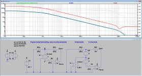
Hi Ian,If you apply the DIT rule to the LT1364 it must be a CFA because it uses a 500 ohm resistor to drive the inverting input.
IH
This is what DIT makes from the LT1364, a pure VFA because Tv is right on top of T.
Hans
Attachments
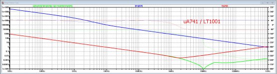
Hi Chris,Still, I see a problem with resorting only to Middlebrook to distinguish them. If I drive a 741's non-inverting input with a voltage source, connect a 100 ohm resistor between its inputs, and employ a 10k impedance feedback network, voila! I have a CFA!
Really?
I didn't use a uA741, but a LT1001, also being a very slow sub 1Mhz GBW amp.
I used the 10K feedback and 100 Ohm between the inputs that you mentioned.
Nevertheless it is by all means still a very convincing VFA with the DIT method.
Hans
Attachments
Hi Chris,
I didn't use a uA741, but a LT1001, also being a very slow sub 1Mhz GBW amp.
I used the 10K feedback and 100 Ohm between the inputs that you mentioned.
Nevertheless it is by all means still a very convincing VFA with the DIT method.
Hans
Huh! My error, I guess. When I changed the "Rg" in my feedback network, the bandwidth remained constant.
I'm left then only with a reluctance to name a circuit by its predominant form of feedback, which can be switched in some cases by simply changing the value of a resistor. That's why I prefer to use the source of the input stage current to name the circuit. This does not change with feedback network resistor values.
There is another thing to consider with the DIT rule: what happens if you make Rf very large?
The ratio of Rf//Rg to 1/gm of the input stage is what tips from CFA to VFA. When Rf is removed we can vary Rg from small value and you have a VFA up to a large Rg and you have a CFA using the Middlebrook/Franco DITrule. In this case with no Rf the transition from VFA to CFA is with NO global feedback. Oh!
So is the DIT method still valid with no Rf? If it is valid then where is the feedback? It must be emitter degeneration of the input stage. Then we must conclude the "F" in CFA and VFA is referring to the input stage local feedback and not the global feedback that we all seem to be discussing.
I think this might be the key to the semantics question. After all, emitter degeneration is current feedback by the classical definition where current of the input stage is sensed by a series resistor and the information is feedback as a voltage (since we have a voltage controlled device we have to convert current to voltage to use it).
So the DIT rule is really only telling us how much degeneration feedback we are using for the input stage.
Cheers,
IH
Ian,
Here is a reply to your other question what happens with a very large Rg.
I used a LT1395 CFA for this experiment.
Rg was made 10Gig and not the get a ridiculous high gain, Rf was made 100K
Looking at the image, it still holds as a CFA, because Ti is much closer to T and still decades from Tv.
I have added a fourth trace V(out) which is the output of the LT1395 when driven with a 1 volt input signal and Rg / Rf resp 10 G and 100K .
This gives you an idea how the transfer function will be under this extreme situation.
So far it seems that the DIT is giving the right answers even to extreme ones.
Hans
Attachments

Oops
Hi Chris, Oops😱. You are right. I can't break the loop and apply DIT. Sorry. My bad. I need to think again.In the referenced article, DIT applies only when there is a global loop. You can't have a return from a forward signal without one.Originally Posted by IanHegglun
When Rf is removed we can vary Rg from small value and you have a VFA up to a large Rg and you have a CFA using the Middlebrook/Franco DITrule. In this case with no Rf the transition from VFA to CFA is with NO global feedback. Oh!
So is the DIT method still valid with no Rf?
Sorry, I misunderstood you.Ummm, no I definitely did NOT echo that. The impedance relationship determines the predominant form of feedback, not the name of the circuit, and not its topology.
We are back to discussing ‘what is a CFA’ - which is what the original thread on this subject tried to answer back in c. 2014. At the time there was quite some confusion with little understanding of the underlying mechanisms or how the current on demand feature worked.
My view was/is that if the current into the TIS/TAS was derived directly from the feedback resistor (not a steered current source as in a VFA) then it was a CFA. It also helps to explain the COD behavior that you do not get with classic MC VFA’s
My view was/is that if the current into the TIS/TAS was derived directly from the feedback resistor (not a steered current source as in a VFA) then it was a CFA. It also helps to explain the COD behavior that you do not get with classic MC VFA’s
- Home
- Amplifiers
- Solid State
- Current Feedback Amplifiers, not only a semantic problem?