My biggest concern is not so much the magnitude of the capacitance, but its non-linearity, since I hope to use this as a buffer to measure distrortion. To do so, it has to drive a notch filter. The notch filter attenuates the fundamental so I can measure very low distortion levels with my 16 bit spectrum analyzer.
With the JFET circuit you recommended, the op amp input will be driven by a lower impedance than the 100k that drives the JFET gates.
The circuit you recommended gave me an idea. Not having a lot of JFETs around, I am looking into a scheme with BJTs. The attached is looking very promising. I just grabbed a wide bandwidth (20MHz) op amp available to my simulator. Although Zin measures in excess of 10Mohms, the op amp input sees only about 1k, something critical to minimize non-linear capacitance distortion. It's just as critical to do this for the transistors. The base-collector ac voltages are 60dB below the input signal and the base-emitters are 110dB down. Response at the output is within .1dB. All values apply across the audio frequency range and are derived using a 100k source. I'm looking forward to testing this.
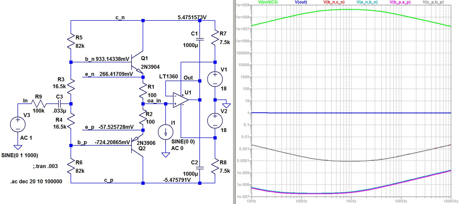
For AC conditions the two 82K Ohm resistors appear in parallel to an effective ground, hence the series 100K Ohm seems feeding an equivalent 41K Ohm to ground. This seems would attenuate the input signal to about 1/3 or 10dB.
Although attenuated, the lowering of the source resistances to the bases increases bandwidth given the combined base/collector capacitances of the NPN and PNP transistors being approx. 8pF (4pF for each device). Hence dropping the source impedances seems would also triple the bandwidth given the capacitances don't change.
Sorry... I see you've coupled the collectors back. Perfect.
I don't think so.
The amplifier itself is designed with real componants.
Controlled sources are there to emulate perfect current or voltage sources that cannot be obtained with physical componants. They are only used to bias or to apply feedback to the amplifier.
As you can see the amp works well with perfect voltage bias and feedback.
No, I don't see that.
That's why I wanted to ask you about a CFA without ideal controlled sources. You even get to specify the circuit. Why the reluctance?
Of course, the circuit works. But the existence of millions of so called CFA topology do not prove their feedback relies on current.
Voltage across Rf, voltage across Rg, voltage across Vbe. A lot of voltages in the current affair.
Dear me for, how much longer can you keep up this pretence.
Do you believe the Americans went to the moon? Probably not if you keep insisting that about 3 or 4 billion CFA IC's manufactured over the last 30 years don't work as advertised.
Using something like a controlled (ideal) current source in a sim has to be done with a lot of care. For one thing, a controlled CCS will pump out whatever current is requested with little concern for reality.
For instance, it will carelessly rise a load voltage to 10kV if that is the product of its current and the load impedance (not saying it does that here, just highlighting a concept).
So if your sim works with a CCS but not with an R, or works with an R but not with a CCS, you need to do some hard thinking rather than jumping to conclusions.
Jan
Till the contrary will be proved to me. Currently, the debate is not going on this direction at all. What we see is that some great names disagree with other great names on the topic.Dear me for, how much longer can you keep up this pretence.
Only a few of them. Maybe I am wrong, but I think that most defenders of the CF concept are american.Do you believe the Americans went to the moon?
CFA ICs are advertised as op-amps first. What characterizes an op-amp, CFA or VFA, is that its inverting input voltage replicates the voltage present at the non-inverting input almost perfectly. The first thing manufacturers advertise is the name op-amp.Probably not if you keep insisting that about 3 or 4 billion CFA IC's manufactured over the last 30 years don't work as advertised.
What manufactuers advertize under the name current feedback is a topology.
This naming is specious to me.
I learned to be wary toward advertisement. Some ICs are advertised as being specially made for audio. How could they ? What's the recipe ? Do customers effectively find them better than standard op-amps in rigourous tests ?
By the way, Marsh and you often say that the Current Feedback topology sounds better. However one of the most revered, subjectively inclined, designer here uses the other feedback topology. Why ?
1. The voltage at the inverting input equals the non inverting input because current flowing through Rg and Re raises or decreases the inverting input voltage, unlike a VFA where the current is of no consequence (because the inv. input impedance is very high. That's why its called a CFA - not because the input voltages are equal in the linear mode.
2. I have never stated current feedback topology sounds better. Kindly find the statement - anywhere - and I will apologize unreservedly for making it. You may have inadvertently got this impression from a previous member who claimed (on many occasions without giving proof when challenged) I made this statement. I never have and have gone to pains to remain completely neutral on the matter.
3. "I think that most defenders of the CF concept are american." No, I don't think this correct.
Last edited:
"I learned to be wary toward advertisement. Some ICs are advertised as being specially made for audio. How could they ? What's the recipe ? Do customers effectively find them better than standard op-amps in rigourous tests ?"
--
I would use a NE5534 or LM4562 (both advertised for audio) and never use a 741. Some opamps are optimised for audio - noise, distortion etc.
--
I would use a NE5534 or LM4562 (both advertised for audio) and never use a 741. Some opamps are optimised for audio - noise, distortion etc.
Maybe I am wrong, but I think that most defenders of the CF concept are american.
This is really getting silly, Barrie Gilbert is most definitely a Brit.
That's why I wanted to ask you about a CFA without ideal controlled sources.
I was surprised that the AD846 data sheet was still up even though it was obsoleted years ago. It has a DC transimpedance of 200M Ohms due to lots of cascoding, etc., that's 166dB Ohms so my second results apply to well below any audio frequencies. So the displacement current in the compensation capacitor (the current into the inverting input) is all that matters at audio frequencies.
I was surprised that the AD846 data sheet was still up even though it was obsoleted years ago. It has a DC transimpedance of 200M Ohms due to lots of cascoding, etc., that's 166dB Ohms so my second results apply to well below any audio frequencies. So the displacement current in the compensation capacitor (the current into the inverting input) is all that matters at audio frequencies.
The 100pF impedance in your asc file seems excessive. The datasheet says something like 4.5pF. If I sim the asc file without any added capacitor, I get frequency response very close to what the datasheet supplies.
No, I don't see that.
That's why I wanted to ask you about a CFA without ideal controlled sources. You even get to specify the circuit. Why the reluctance?
Once again, the CFA itself is made of real componants, transistors and resistors.
Controlled sources are external virtual componants because I need perfect voltage and current sources.
IMHO, it would be more constructive to tell us what you see instead of only saying that you disagree on this point.
The 100pF impedance in your asc file seems excessive. The datasheet says something like 4.5pF. If I sim the asc file without any added capacitor, I get frequency response very close to what the datasheet supplies.
That sim has nothing to do with the AD844 or AD846, nothing at all, the transistors and process are totally different. Putting 3904's and 3906's into a simplified AD844 schematic is not simulating the AD844. I'm expecting too much, I appologize, stuff like this can only be done person to person the chat forum process simply can't work.
Once again, the CFA itself is made of real componants, transistors and resistors.
Controlled sources are external virtual componants because I need perfect voltage and current sources.
IMHO, it would be more constructive to tell us what you see instead of only saying that you disagree on this point.
The problem is that I don't follow your argument.
I was hoping to ask you a simple question about a sim result in a CFA made without controlled sources. Scott Wurcer provided one only a few posts back. I provided one in post 1028. If you accept either as realistic, let me know. Or supply one that you prefer.
That sim has nothing to do with the AD844 or AD846, nothing at all, the transistors and process are totally different. Putting 3904's and 3906's into a simplified AD844 schematic is not simulating the AD844. I'm expecting too much, I appologize, stuff like this can only be done person to person the chat forum process simply can't work.
Right, but I put the '04's and '06's in an LT1395 sim and you put different transistors in the AD844 sim. But I certainly take your point about process differences.
Yes, this chat forum thing is frustrating - it really limits our ability to communicate. And it too often leaves us thinking to ourselves that the other is a blithering idiot, when the real problem is that "What we have here is a failure to communicate!"
I apologize too.
Using something like a controlled (ideal) current source in a sim has to be done with a lot of care. For one thing, a controlled CCS will pump out whatever current is requested with little concern for reality.
For instance, it will carelessly rise a load voltage to 10kV if that is the product of its current and the load impedance (not saying it does that here, just highlighting a concept).
So if your sim works with a CCS but not with an R, or works with an R but not with a CCS, you need to do some hard thinking rather than jumping to conclusions.
Jan
Jan,
Please, before saying that I didn't hard think on the subject, I would appreciate that you do not distort my conclusions.
The best way to know if the sim is realistic or not is to run it and analysed the results, but may be I'm wrong on this statement.
Wikipedia said he is an english-american and he emigrated to the United States in 1964.Originally Posted by forr
Maybe I am wrong, but I think that most defenders of the CF concept are american.
This is really getting silly, Barrie Gilbert is most definitely a Brit.
Barrie Gilbert - Wikipedia
The problem is that I don't follow your argument.
I was hoping to ask you a simple question about a sim result in a CFA made without controlled sources. Scott Wurcer provided one only a few posts back. I provided one in post 1028. If you accept either as realistic, let me know. Or supply one that you prefer.
Chris, please, what is the argument you don't follow ?
How can you disagree with the fact that the sim works with voltage feedback ?
I am afraid to tell you that I don't understand what you want to demonstrate in your post 1028.
I do not understand why your numbers are incompatible with the fact that we are in presence of voltage feedback.
I was surprised that the AD846 data sheet was still up even though it was obsoleted years ago. It has a DC transimpedance of 200M Ohms due to lots of cascoding, etc., that's 166dB Ohms so my second results apply to well below any audio frequencies. So the displacement current in the compensation capacitor (the current into the inverting input) is all that matters at audio frequencies.
I still have some '846's.
BTW I am proud to be Dutch. Though some of my best friends are Americans. And French. And Germans. And Brits. Even a few French.
Bringing someone's statehood into a tech discussion is absurd, insulting and plain stupid. Good thing there is an ignore list on this forum.
Jan
Chris, please, what is the argument you don't follow ?
How can you disagree with the fact that the sim works with voltage feedback ?
I am afraid to tell you that I don't understand what you want to demonstrate in your post 1028.
I do not understand why your numbers are incompatible with the fact that we are in presence of voltage feedback.
It's not that you can't find a needlessly complex way to describe this phenomenon as voltage feedback; it's that you can more simply describe it as current feedback.
Post 1028 summary: The voltage feedback paradigm demands that the transistor is acting mainly as a transconductor. In a transistor, transconductance gm is I(DC) / 26mV at room temperature. That means that the ratio of AC parameters ic/vbe should equal gm. But if you measure it in the Post 1028 sim or in Scott Wurcer's sim, it definitely doesn't.
Post 1028 explains what is happening. Transconductance is happening, but the Early Effect is significant, because the loop gain is so high that it drives vbe to such low levels that the contribution from transconductance is on the same order as that from the Early effect (the loop gain doesn't reduce vce.) So now we have an additional (effectively resistive) path from the emitter to the collector.
Of course you can say that this is voltage feedback because the voltage between the emitter and base drives a transconductance to create a current which is added to another current created by the difference between the emitter and collector voltages divided by what is effectively a resistor to become a single current flowing through the collector.
Or, noting that the emitter and collector currents are almost identical, you can say you have current feedback.
It's not necessarily wrong to describe this as voltage feedback (see 2 paragraphs above), but even without the Early effect, it's less complex and more straight forward to describe it as current feedback. With the Early effect, there's no comparison.
Last edited:
- Home
- Amplifiers
- Solid State
- Current Feedback Amplifiers, not only a semantic problem?