The attached was designed many years ago to measure AC signals from the chemical reactions in the brain of some small rodents. It works on the principle of nulling feedback capacitances by tracking and maintaining the drain voltage to the gate and the gate voltage to the source.
The high impedance op amp prevents the variance in the drain/source current as would then cause voltage variations between the grid and source. I am not sure if I actually doubled the stacking of the FET's.
Thanks much, Hierfi! JFET/MOSFET input op amp? Recommendations for JFETs?
Yes, see Dadod, above. Or, my headphone amp design. With some additional tweeking/trim it got down to the analyser floor (AP 2722). The input devices are low C jFET's (HF/RF) but in this CMA configuration the C's effect cancel, anyway...
THx-RNMarsh
Thanks, but I'm a bit confused. Your headphone amp above was a four-BJT CMA with an OPS added. (dadot's design had the JFETs.) Did you achieve -130dB or better THD with it? Were the tweaks for bias current matching?
Thanks, but I'm a bit confused. Your headphone amp above was a four-BJT CMA with an OPS added. (dadot's design had the JFETs.) Did you achieve -130dB or better THD with it? Were the tweaks for bias current matching?
No. Thats not the headphone amp design. That's the first CMA ever being used as a line driver.
See Linear Audio publication for complete details or go to the DIYAudio headphone amp forum to find it. Basically, you have to find/select from a batch a true compliment FET's and trim circuit values to get a near perfect C cancellation. Because the distortion comes from the jFET's non-linear C.
SIM's probably do not include it. Does it?
THx-RNMarsh
Last edited:
Thanks much, Hierfi! JFET/MOSFET input op amp? Recommendations for JFETs?
My memories are vague, rather only remembering the principles. I seem to recall using JFET's like 2N5460's, 2N5457, 2N5485's and 2N5486's for reasons they had lower intrinsic capacitance's than MOSFETs. This meant less capacitance to null. Higher IDSS devices like the 2N5486 were used as stacked in order to allow a voltage drop across the input device, like a low IDSS 2N5457 or 2N5460. It seems in retrospect that you could use all high IDSS devices of both N and P- Channel and connect a variable resistor of perhaps 5 K Ohm between the input sources and then use the wiper to trim for zero
The question I asked to myself today :
can we still speak of a CFA when the impedance the feedback network is hugely smaller than the impedance of the inverting output ?
Hi forr,
I asked myself another question : How can we prove a "CFA" is voltage or current feedback ?
Reply is easy : you edit a simulation with a CFA, then you insert a pure current feedback and you see if it works, you do the same with pure voltage feedback and you will have your reply.
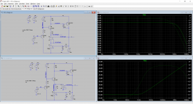
So here is the simulation schemes :

Lower schematics : pure current feedback. 2 voltage controlled current sources, one (G2) delivering the bias current of input stage, the other one delivering a current proportional to the output.
Result is on the right : It doesn't work.
Upper schematics: pure voltage feedback, 2 serial voltage controlled voltage sources . One (E1) delivering the bias voltage of input stage, the other one delivering voltage proportional to the output V = S/100.
Result is on the right : It works. the gain is determined by the ratio of the feedback voltage controlled voltage source.
So we can conclude that "CFA" are not current feedback amplifiers.
"CFA" are purely voltage feedback amplifier.
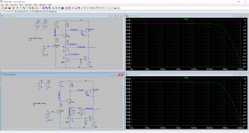
Now, if we take the schematics with current feedback and add a resistor between inverting input and reference,

It works.
It works because resistors develop voltage with the current and because CFA needs low impedance at the inverting input to have gain, low impedance source is voltage source.
CFA are voltage feedback amplifier.
Hervé, if you would attach the circuit diagrams to the post rather than embedding them, we might be able to read them.
Jan
Jan
Hi Jan,Hervé, if you would attach the circuit diagrams to the post rather than embedding them, we might be able to read them.
Jan
Sorry, let's try again.
Attachments
Thanks. So, what is the point here? I think you set the emitter voltage in both cases to 10mV per volt Vout. And you get the same results, to be expected.
Not sure what that has to do with CFA or VFA? Am I missing something?
Jan
Not sure what that has to do with CFA or VFA? Am I missing something?
Jan
Thanks. So, what is the point here? I think you set the emitter voltage in both cases to 10mV per volt Vout. And you get the same results, to be expected.
Not sure what that has to do with CFA or VFA? Am I missing something?
Jan
Jan,
In the left pic, upper is a voltage feedback which works and lower is a current feedback which doesn't work.
In right pic current feedback works because of the resistor which create low impedance voltage with the current.
The point is that if feedback send only current to the inverting input, you have no gain. Then it is not possible to speak about current feedback because it works only with voltage.
Well the problem with that is of course that in real live the current feedback works, in thousands if not millions of pieces of equipment.
So if in your sim it doesn't work you have just proved that your sim is in conflict with reality.
And don't forget that in reality the feedback current resistor is important to the operation. In your sim, the current only depends on Vout. In real life, the current depends on the voltage difference across the resistor.
Try to replace the current source with a real resistor and see what happens. I think it will 'work' then.
Jan
Last edited:
Of course, the circuit works. But the existence of millions of so called CFA topology do not prove their feedback relies on current.Well the problem with that is of course that in real live the current feedback works, in thousands if not millions of pieces of equipment.
Voltage across Rf, voltage across Rg, voltage across Vbe. A lot of voltages in the current affair.In real life, the current depends on the voltage difference across the resistor.
Thanks much, Hierfi! JFET/MOSFET input op amp? Recommendations for JFETs?
In looking at some op amps the common mode capacitance seems around 5 pF. This suggests that for a 100K Ohm series input (the output impedance of your tube circuit?) the bandwidth is approx. 300KHz. Are you looking for more bandwidth than this?
I am suspecting the circuit provided is less than 1 pF common mode, although I would do some simulations with a 100K Ohm in series to determine the expected bandwidth. This will give you some idea of the actual capacitance as well. Also bear in mind that lower drain to source voltages increases capacitances. Using high IDSS or "zero gate voltage drain current" devices under low current conditions raises the voltage drops across the FET's beneath them.
In further recall, the device was built as a battery operated (2 x 9volt) probe in close proximity to the "subject" and inside a Faraday room. Once you get to sub picoFarad capacitances care must be taken in circuit layout, design and application to prevent stray capacitances from affecting measurements.
Well the problem with that is of course that in real live the current feedback works, in thousands if not millions of pieces of equipment.
So if in your sim it doesn't work you have just proved that your sim is in conflict with reality.
Sophism.
The sim works for pure voltage feedback and is in perfect agreement with reality. As millions of pieces of equipment.
And don't forget that in reality the feedback current resistor is important to the operation.
But why does a current feedback need a resistor ?
The sim with voltage feedback doesn't need resistor
In your sim, the current only depends on Vout. In real life, the current depends on the voltage difference across the resistor.
Try to replace the current source with a real resistor and see what happens. I think it will 'work' then.
Jan
So, you call "current feedback" something which needs a resistor to have a voltage.
In looking at some op amps the common mode capacitance seems around 5 pF. This suggests that for a 100K Ohm series input (the output impedance of your tube circuit?) the bandwidth is approx. 300KHz. Are you looking for more bandwidth than this?
I am suspecting the circuit provided is less than 1 pF common mode, although I would do some simulations with a 100K Ohm in series to determine the expected bandwidth. This will give you some idea of the actual capacitance as well. Also bear in mind that lower drain to source voltages increases capacitances. Using high IDSS or "zero gate voltage drain current" devices under low current conditions raises the voltage drops across the FET's beneath them.
In further recall, the device was built as a battery operated (2 x 9volt) probe in close proximity to the "subject" and inside a Faraday room. Once you get to sub picoFarad capacitances care must be taken in circuit layout, design and application to prevent stray capacitances from affecting measurements.
My biggest concern is not so much the magnitude of the capacitance, but its non-linearity, since I hope to use this as a buffer to measure distrortion. To do so, it has to drive a notch filter. The notch filter attenuates the fundamental so I can measure very low distortion levels with my 16 bit spectrum analyzer.
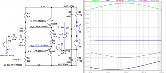
With the JFET circuit you recommended, the op amp input will be driven by a lower impedance than the 100k that drives the JFET gates.
The circuit you recommended gave me an idea. Not having a lot of JFETs around, I am looking into a scheme with BJTs. The attached is looking very promising. I just grabbed a wide bandwidth (20MHz) op amp available to my simulator. Although Zin measures in excess of 10Mohms, the op amp input sees only about 1k, something critical to minimize non-linear capacitance distortion. It's just as critical to do this for the transistors. The base-collector ac voltages are 60dB below the input signal and the base-emitters are 110dB down. Response at the output is within .1dB. All values apply across the audio frequency range and are derived using a 100k source. I'm looking forward to testing this.
Attachments
Hi forr,
I asked myself another question : How can we prove a "CFA" is voltage or current feedback ?
Would you kindly post your .asc files?
Would you kindly post your .asc files?
Sure.
Attachments
Sure.
I'd like to ask a question about a simple (few transistor) CFA of your choice, the only restriction being that it contains no ideal controlled sources, only transistors and resistors. (Independent constant current and voltage sources are OK.)
Would you care to propose and post an asc file for consideration?
I don't think so.
The amplifier itself is designed with real componants.
Controlled sources are there to emulate perfect current or voltage sources that cannot be obtained with physical componants. They are only used to bias or to apply feedback to the amplifier.
As you can see the amp works well with perfect voltage bias and feedback.
- Home
- Amplifiers
- Solid State
- Current Feedback Amplifiers, not only a semantic problem?