Drive the non-inverting input of a VFA with a voltage source. Connect a low resistance r between the two inputs. As Rg is varied over the range where r < Rg || Rf, there will be a CFA-like constant bandwidth, but no CFA-like slew rate enhancement. Certainly the topology of the VFA is not CFA-like. Since no significant current enters the VFA gain block, I wouldn't call this current feedback.
As with any of these thought experiments it helps everyone to specify it fully. A 100MHz GBW VFA configured to give ~100MHz BW at G of 1 to 10 with simply external resistors would be interesting. Putting an amplifier into a noise gain of 100 so the BW at G = 1 to 10 is constant is not so interesting.
As with any of these thought experiments it helps everyone to specify it fully. A 100MHz GBW VFA configured to give ~100MHz BW at G of 1 to 10 with simply external resistors would be interesting. Putting an amplifier into a noise gain of 100 so the BW at G = 1 to 10 is constant is not so interesting.
Sorry to keep referencing this, but an actual bench test of this claim can be found in Current Feedback: Fake News or the Real Deal? | audioXpress . Not the 100MHz thing - I'll leave that to Scott.
Last edited:
As with any of these thought experiments it helps everyone to specify it fully. A 100MHz GBW VFA configured to give ~100MHz BW at G of 1 to 10 with simply external resistors would be interesting. Putting an amplifier into a noise gain of 100 so the BW at G = 1 to 10 is constant is not so interesting.
Also, please recall that this not so interesting response was an answer to forr's question in post number 1076.
Umm. You dont need the current enhancement of a diamond input stage nor diamond output stage nor even the current mirror to operate as CMA/CFA. For audio, high bias class A operation at suitable level gets the job done.
All you need to see---
"Amplifiers that employ current feedback can readily exhibit
constant bandwidth with varying closed loop gain. All that is needed
is for the network impedance Req seen by the inverting input to be
kept larger than that input’s impedance ZFB".
Thus, for audio, a greatly simplified schematic can result.
THx-RNMarsh
Didnt say that but you are entitled to your ill informed opinion.
Yes you did and so are you. And no one here has put forth any kind of credible technical argument as to why a properly designed CFA should "almost always" sound better than a properly designed VFA. All you have is bluster and mystic allusions to your alleged higher understanding.
Sorry to keep referencing this, but an actual bench test of this claim can be found in Current Feedback: Fake News or the Real Deal? | audioXpress . Not the 100MHz thing - I'll leave that to Scott.
You mean your figure 6, I didn't peek but I knew what you were talking about? You put an amplifier in a noise gain of 100 and get 1/100 the BW and the closed loop gain resistors don't materially change the noise gain so there is little change in the closed loop BW. This is neither surprising or interesting, the shunt 100 Ohm resistor is not part of the input stage transfer function. With all due respect this has nothing to do the current argument and maybe it should just pass.
You mean your figure 6, I didn't peek but I knew what you were talking about? You put an amplifier in a noise gain of 100 and get 1/100 the BW and the closed loop gain resistors don't materially change the noise gain so there is little change in the closed loop BW. This is neither surprising or interesting, the shunt 100 Ohm resistor is not part of the input stage transfer function. With all due respect this has nothing to do the current argument and maybe it should just pass.
Unfortunately, it does. It is a response to forr's question in post 1076. Nothing more.
Yes you did and so are you. And no one here has put forth any kind of credible technical argument as to why a properly designed CFA should "almost always" sound better than a properly designed VFA. All you have is bluster and mystic allusions to your alleged higher understanding.
Apparently you havent been here following this subject for the past 2- 3 years. enough said.. you dont know what you are talking about.
-RNM
In a very few words my approach consists in considering the voltage at the inverting input and the load it sees. If you want, I can look for the posts where I exposed it.Would you care to reacquaint us with your approach?
These days I was thinking of the transistors of the inverting output : can they be considered as operating in common base. My conclusion is that they can be common base only if the inverting load is a current source or if they are ideal.
Today I reread some texts I somewhat forgot on the topic.
Among them, Sergio Franco
https://www.edn.com/electronics-blo...ansistor-?utm_source=Aspencore&utm_medium=EDN
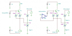
Your statement 'Whether feedback is called "voltage" or "current" is misleading' does not hold in the case of Fig. 6b. If you ground the input (Vi = 0), break the loop at the CFA's output, and inject a test signal into the feedback network to see what comes back to the CFA's inverting input, you see just a current - no voltage is fed back, as the input buffer keeps Vn fixed at 0 V. So, you can only refer to this state of affairs as "current feedback". You then easily see that the forward gain is zc, the feeback factor is 1/R2, and the loop gain is T = zc/R2. In practice, the input buffer is not ideal as in Fig. 6, but exhibits some small non-zero output impedance zn.
Sergio Franco, Walter Jung and many other authors are conscious of the imperfection of the buffer.
I simulated Franco's above proposed experience with my simplified CFA input stage. On the circuit on the right, the transistor is made ideal using an ideal op-amp. The currents and voltages make very clear that real CFA occurs only with unrealistic ideal transistors which allows a null impedance inverting input.
Certainly we do not live in perfection but I think that, there, the imperfection is noticeable enough to contest the current feedback concept.
Attachments
"Amplifiers that employ current feedback can readily exhibit
constant bandwidth with varying closed loop gain. All that is needed
is for the network impedance Req seen by the inverting input to be
kept larger than that input’s impedance ZFB".
Thus, for audio, a greatly simplified schematic can result.
I wouldn't consider any of the schematics presented "simple". You forget the audio PA is a captive application with a set closed-loop gain and none of the issues for making a general purpose product apply. You can optimize the internals of a degenerated or H-bridge VFA to offer all the attributes of an equivalent CFA. Don't forget the Otala amp.
In a very few words my approach consists in considering the voltage at the inverting input and the load it sees...
These days I was thinking of the transistors of the inverting output : can they be considered as operating in common base. My conclusion is that they can be common base only if the inverting load is a current source or if they are ideal.
First question: Why?
Second question: Even if true, what relevance is there to the question of current feedback?
Today I reread some texts I somewhat forgot on the topic.
Among them, Sergio Franco
https://www.edn.com/electronics-blo...ansistor-?utm_source=Aspencore&utm_medium=EDN
Your statement 'Whether feedback is called "voltage" or "current" is misleading' does not hold in the case of Fig. 6b.
I looked at the blog. I don't see any of my comments there.
Sergio Franco, Walter Jung and many other authors are conscious of the imperfection of the buffer.
As am I.
I simulated Franco's above proposed experience with my simplified CFA input stage. On the circuit on the right, the transistor is made ideal using an ideal op-amp. The currents and voltages make very clear that real CFA occurs only with unrealistic ideal transistors which allows a null impedance inverting input.
Certainly we do not live in perfection but I think that, there, the imperfection is noticeable enough to contest the current feedback concept.
I do not understand why the lack of an ideal CFA input stage debunks the claim of current feedback anymore than the lack of an ideal VFA input stage debunks the claim of voltage feedback.
Final question: Will you respond to post 1028?
I wouldn't consider any of the schematics presented "simple". You forget the audio PA is a captive application with a set closed-loop gain and none of the issues for making a general purpose product apply. You can optimize the internals of a degenerated or H-bridge VFA to offer all the attributes of an equivalent CFA. Don't forget the Otala amp.
I dont either. Just that to be a CMA it can be made much simpler for audio is my only point.
And. no i have not forgotten ..... in fact, I have been long ago looking at the more advanced and complex designs into RF/Microwaves. The book I recommended ($106) and bought is a case in point far beyond the nitch of audio.
This IS an audio only forum. So, my comments apply specifically to the audio app/community.
THx-RNMarsh
Last edited:
Small consolation, move on there is nothing here.
When you can't pay attention to your own advice, that's a problem. Cured.
Just that to be a CMA it can be made much simpler for audio is my only point.
THx-RNMarsh[/QUOTE]
THx-RNMarsh[/QUOTE]
Last edited:
Apparently you havent been here following this subject for the past 2- 3 years. enough said.. you dont know what you are talking about.
Unreal. If there was only a single contributor to this "debate" who could be said to have never betrayed an understanding of anything, that person would be you.
Unreal. If there was only a single contributor to this "debate" who could be said to have never betrayed an understanding of anything, that person would be you.
🙄
Just that to be a CMA it can be made much simpler for audio is my only point.
-RM
Last edited:
🙄
Just that to be a CMA it can be made much simpler for audio is my only point.
-RM
Oh, very good. Given that your are re-quoting in response to me a response to scott wurcer from a discussion of something else, I guess that in addition to the qualities I ascribed to you earlier I can now add the debating tactics of a clown.
2 to 3 years (?) of scholarly (*cough*) inquiry and you still can't instantly summarize a single magical defining characteristic of CFAs which supports your assertion that they "almost always sound better" than VFAs ?
- Home
- Amplifiers
- Solid State
- Current Feedback Amplifiers, not only a semantic problem?