Yes - excellent name!
I could of course use other words in there ;-)I did not like feedback - however, I do - whether its voltage or current!
I could of course use other words in there ;-)I did not like feedback - however, I do - whether its voltage or current!
It's always good to give each other positive feedback about negative feedback! 😱
Jan
Jan
Last edited:
I love the FFA acronym! It nicely addresses the historical "name" problem.
Unfortunately, it does nothing to address the differences in the ways that those posting in this thread understand how classical CFAs work.
Unfortunately, it does nothing to address the differences in the ways that those posting in this thread understand how classical CFAs work.
I like it. Happily it could also mean Fancy Feedback Amplification.
EDIT : .... or, with pretention, Forr's Feedback Amplification.
EDIT : .... or, with pretention, Forr's Feedback Amplification.
Last edited:
Design Techniques for Current-Mode Circuits | SpringerLink
Good book.
THx-RNMarsh
Design Techniques for Current-Mode Circuits
amplifier to a unit-step input has an overshoot of 4.32% approximately [46]. Fig.2.15 shows the dependence of the bandwidth of the current amplifier with the resistor series peaking on the resistance of the peaking resistor.
©-^1 ^2® lo
i^[-4AAri-||M2
-^
Figure 2.14- Basic current amplifier with resistor series peaking.
Figure 2.15. Simulated frequency response of current amplifier with resistor series peaking. R is varied from 0 to 1.5 kO, with step 0.375 kQ. The amplifier is implemented in TSMC0.18)LAm CMOS technology.
2.6.2 Inductor Series Peaking The thermal noise of the series peaking resistor increases the total noise of the amplifier. For low-noise apphcations, such as the frontend of Gb/s transceivers and optical pre-amplifiers, noiseless elements, such as inductors, are preferred over noisy resistors for bandwidth enhancement. It has been demonstrated that inductor shunt peaking can increase the bandwidth of voltage-mode circuits by as much as 70% [47, 48]. Inductor shunt-peaking technique, however, is not particularly applicable to current-mode circuits due to the existence of biasing current sources between the devices forming the dominant poles and the supply voltage. The fact that the dominant pole of the basic current amplifier is located at the gates of Mi and M2 suggests that an inductor can be placed between the gates of Mi and M2, as shown in Fig.2.16, to boost bandwidth. By assuming Cgs2^Cgsi^ we obtain the current transfer function
Iin{s) ~ \9ml) S^LCgs2 + S^ + 1
(2.33)
9ml
The two poles are located at
Last edited:
Holy Moses what have you been drinking or smoking?
What exactly has this to do about Current Feedback Amplifiers? 😕
What exactly has this to do about Current Feedback Amplifiers? 😕
I love the FFA acronym! It nicely addresses the historical "name" problem.
.
There is one that is too offensive and tasteless to list.
FFA Future Farmers of America
FFA Free Fatty Acid
FFA Free For All
FFA Forum Fisheries Agency
FFA Fédération Française d'Athlétisme (French: French Athletics Federation)
FFA Federal Facility Agreement
FFA Framework for Action
FFA Forces Françaises en Allemagne (French: French Forces in Germany)
FFA Fund for Animals
FFA Federal Financial Aid
FFA Forum Francophone des Affaires (French: Francophone Business Forum)
FFA Forward Freight Agreement
FFA Fundus Fluorescein Angiography (ophthalmological test)
FFA Free File Alliance (income taxes)
FFA Framför Allt
FFA Fédération Française de l'Acier (French: French Steel Federation)
FFA Final Fantasy Adventure (game)
FFA Fellow of the Faculty of Actuaries
FFA Fédération Française d'Aérostation (French: French Ballooning Federation; est. 1977)
FFA Farmers for Action (UK)
FFA Flygtekniska Försöksanstalten (Aeronautical Research Institute of Sweden)
FFA Final Fantasy Anthology (game package with Final Fantasy 5 and 6)
FFA Female Fat Admirer
FFA free-fire area (US DoD)
FFA Food for Assets
FFA Freedom for Animals
FFA Florida Forestry Association
FFA Functional Failure Analysis
FFA Face Fusiform Area
FFA Forest Fire Association (Nelspruit, South Africa)
FFA Food and Foodstuff Association (of Ho Chi Minh City, Vietnam)
FFA Full Freight Allowed
FFA Financial Funds Advisors International
FFA Form Factor Accurate (Qualcomm)
FFA Florida Fruit Association
FFA Flammable Fabrics Act of 1953
FFA Final Flash Association
FFA Finnish Forest Association
FFA Florida Flute Association (Bradenton, FL)
FFA Free-Flight Airspace
FFA Finite Field Arithmetic
FFA Family Faculty Association
FFA Forest Farmers Association
FFA Food For Agriculture (WHO)
FFA Final Fantasy Addicts (website)
FFA Frankfort Arsenal
FFA Fletcher Farr Ayotte PC (Portland, Oregon)
FFA French Forces in Germany (Forces Francaises en Allemagne)
FFA F”reningen F”r Arbetarskydd (Sweden)
FFA Fire Fighting Appliance
FFA Failed Fuel Assembly
FFA Functional Flow Analysis (Bellcore)
FFA Florida Family Action
FFA Free Freight Allowance
FFA Family Funeralhome Association (est. 1989)
FFA Fellow, Institute of Financial Accountants
FFA Filter Fan Assembly
FFA Fan Film Awards
FFA Field Force Automation
FFA Flow of Funds Accounts
FFA Far Far Away
FFA Football Federation of Australia (soccer/football, Australia)
FFA Fieselfreunde Augsburg
FFA Force Field Analysis (psychological technique)
FFA Football for All (various locations)
I like it. Happily it could also mean Fancy Feedback Amplification.
EDIT : .... or, with pretention, Forr's Feedback Amplification.
Well, that would be amusing!
I have some simulation results that appear to invalidate something I once thought was at least a legitimate statement about CFA operation: I had believed that the transfer function of the inverting input transistors is a simple transconductance.
No more!
The collector-emitter output impedance ro becomes a significant player when the loop gain drives the AC vbe to very low values. Allow me to present some data to support this claim.
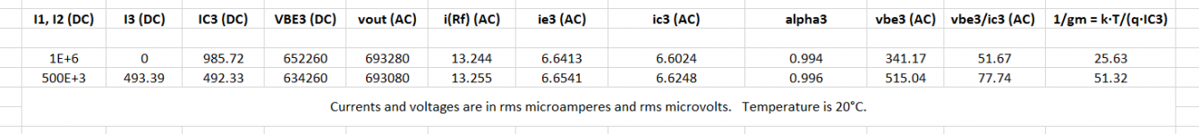
The first attached schematic and LTSpice file is a discrete transistor simulation of the “simplified schematic” found in the LT1395/LT1396/LT1397 datasheet. I have replaced the input transistor (Q1, Q2, Q3 and Q4) bias components with simple DC current sources I1 and I2. Varying these allows experimentation with input transistor transconductances. Source I3 compensates all other transistors for these variations and holds their biases and therefore operating points constant. Accordingly, the circuit’s demand of ic3 AC current is also held constant. The five simple circuits arranged vertically on the right support the measurement of the AC-only signals vbe3, vce3, ie3, ic3 and i(Rf). I’ve collected data for two different sets of biases. Results are in the table below.
As expected, the transconductances as calculated by the reciprocal of vbe3/ic3 differ noticeably due to the change in operating point – by a factor of about 1.5 - but the AC voltages and currents and the alpha ratio of ic3/ie3 differ hardly at all – by no more than 0.4%, and typically much less than that. Significant variations in transistor transconductance simply have no effect on the rest of the circuit’s performance (except for the amplitude of vbe3!). It is the transimpedance of the total gain block which is critical.
This point alone does not support the surprising claim at the beginning of this post. But there’s another issue - the mystery here: why are ic/vbe calculations so different from those of the standard transconductance calculation IC·q/(k·T)? The answer is the transistor resistance ro between the collector and emitter, which is in parallel with the vbe-controlled current source. In many cases we can ignore ro in comparison to gm·vbe. But as we shall see, not in this one! The high loop gain drives vbe to very small values, and vce/ro becomes significant in comparison to gm·vbe.
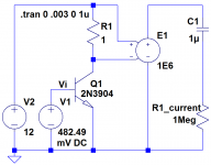
Consider the second schematic and LTSpice file. Here, to calculate gm, we simulate the AC collector current produced by the AC portion of the vbe voltage when VCE is held constant at 12V. We then calculate ro by simulating the AC collector current produced by the AC portion of the V2 voltage when VBE is held constant. Both AC voltages arise in the first schematic from the application of a 1kHz 1 volt peak Vin signal. Here are the results:
Now we see that the transconductance reciprocal v1/i(R1) (AC) in the second table is much closer to that calculated from the IC3 DC current in the first table. And, since the two AC collector currents in the second table subtract rather than add, we calculate the total current to be 6.6815uA, which gives us something very close to the AC collector current ic3 of the first table.
The conclusion is clear: The transconductance paradigm alone cannot explain the operation of this particular CFA, and therefore cannot be counted on to do so reliably for any other. And so, the voltage feedback explanation of CFA operation fails. But the current feedback explanation is untarnished by the results of this investigation. Nor will the ratio of these two currents in any other CFA sully it.
Attachments

Holy Moses what have you been drinking or smoking?
What exactly has this to do about Current Feedback Amplifiers? 😕
Design techniques for current mode circuits? Oh, quit a lot, actually.
Suggested reading. Book cost $106 USD
THx-RNMarsh
Last edited:
The conclusion is clear: The transconductance paradigm alone cannot explain the operation of this particular CFA, and therefore cannot be counted on to do so reliably for any other. And so, the voltage feedback explanation of CFA operation fails. But the current feedback explanation is untarnished by the results of this investigation. Nor will the ratio of these two currents in any other CFA sully it.
🙂 😎
-RNM
Scott, I can play that game too 😀 :
CFA Chartered Financial Analyst
CFA Current feedback amplifier
CFA Country Fire Authority (Victoria State, Australia)
CFA College of Fine Arts
CFA Center For Astrophysics (Cambridge, MA)
CFA Cat Fanciers' Association, Inc.
CFA California Faculty Association
CFA Canadian Franchise Association
CFA Consumer Federation of America
CFA Chick-fil-A
CFA Center For Architecture (JIEO)
CFA Color Filter Array
CFA Certified Financial Analyst (professional certification)
CFA Commercial Finance Association
CFA Conselho Federal de Administração (Brazil)
CFA Confirmatory Factor Analysis
CFA Communaute Financiere Africaine (French: African Financial Community)
CFA Canadian Federation of Agriculture
CFA Complete Freund's Adjuvant
CFA Cease-Fire Agreement
CFA Commission of Fine Arts (Washington, DC)
CFA Chinese Football Association
CFA CompactFlash Association
CFA Central Facilities Area
CFA Commonwealth Forestry Association (UK)
CFA Cryptogenic Fibrosing Alveolitis
CFA Call for Abstracts
CfA Council for Administration (UK)
CFA Continuous Flow Analysis
CFA California Fashion Association
CFA Chilled Food Association (UK)
CFA Common Femoral Artery
CFA College Football Association
CFA Canadian Forestry Association
CFA Contract Flooring Association
CFA Conditional Fee Arrangements (insurance)
CFA Constituency for Africa
CFA Committee on Fiscal Affairs (Organisation for Economic Co-Operation and Development)
CFA Current Feedback Amplifier
CFA Confirmatory Factor Analytic (model)
CFA Connecting Facility Assignment
CFA Control Flow Analysis
CFA California Forestry Association
CFA Communauté Financière d'afrique (French: African Financial Community)
CFA Canned Food Alliance
CFA Catfish Farmers of America
CFA Campus Freethought Alliance
CFA Coefficient of Fat Absorption
CFA Concrete Foundations Association
CFA Come from Away (Newfoundland, Canada)
CFA Central Fiscal Authority (Kosovo)
CFA Conditioned Floor Area (heating & cooling)
CFA Certified Forensic Accountant
CFA Corporate Financial Advisory
CFA Certified Financial Accountant (professional certification)
CFA Continence Foundation of Australia
CFA Code Field Address
CFA Cognizant Federal Agency
CFA Conservation Finance Alliance (biodiversity funding organization; est. 2002)
CFA Call for Action, Inc.
CFA Canadian Foundry Association
CFA Circus Fans Association of America
CFA Covering Force Area
CFA Case For Action
CFA Canadian Flag Association
CFA Comité Français des Aérosols
CFA Carrier Facility Assignment
CFA Continuous Flight Auger Pile
CFA Communication Foundation for Asia
CFA Centre de Formations d'Apprentis (France)
CFA Cognizant Field Activity
CFA Confédération Française de l'Aviculture (French: French Confederation of Poultry)
CFA Cascadia Forest Alliance
CFA Cooperation Framework Agreement
CFA Consello d'A Fabla Aragonesa (Aragonese Language Council)
CFA Company Formation Agent (UK)
CFA Craniofacial Foundation of America
CFA Committee on Food Aid Policies and Programmes (United Nations)
CFA Conversation For Action
CFA Citizens Flag Alliance, Inc.
CFA Charles F. Adams (DDG-2, US Guided Destroyer Class ship)
CFA Component Failure Analysis
CFA California Flight Academy
CFA Chief Financial Advisor
CFA Cards from Africa (est. 2004)
CFA Crossed Field Amplifiers
CFA Controlled Firing Area (aviation)
CFA Cross Field Antenna
CFA Circuit Facility Assignment
CFA Cross Field Amplifier
CFA Carrier Failure Alarms
CFA Current Files Area
CFA Commission for Law Enforcement Accreditation
CFA California Fertilizer Association
CFA Children First America
CFA Center for Action
CFA Combined Field Army
CFA Call-Forward Area
CFA Conformal Array
CFA Customer Facility Assignment
CFA Certified First Assist
CFA Computerized Fleet Analysis, Inc.
CFA Community Forestry International
CFA Congregatio Fratrum Alexianorum (Alexian Brothers; religious order)
CFA Crytogenic Fibrosing Alveolitis
CFA Courses Féminines Associées (French: Associated Women's Racing)
CFA Car Forwarding Agency
CFA Control Facilities Area
CFA Composite Fabricator's Association
CFA Christian Farmers Association
CFA Carrier Facility Alarm
CFA Canadian Football Association
CFA Change in Frame Alignment
CFA Closed Form Analysis
CFA Cadet Fitness Assessment (US DoD military academies)
CFA Corrugated Feeder Antenna
CFA Cascading Failure Analysis
CFA Communications Functional Area
CFA Contract Funding Available
CFA Control Fighter Airspace
CFA Cognizant Federal Authority
CFA Catarman Fishermen Association
CFA Cercle France Afrique (France)
CFA Call Flow Analysis
CFA Carrier Frequency Acquisition
CFA Current Force Assessment
CFA Centro de Futebol Amazônia Ltda (Brazil)
CFA Cachagua Fire Auxiliary (Carmel Valley, CA)
CFA Code Function Assignment
CFA Conditions for Acceptance (various organizations)
CfA Centre for Archaeology (UK)
CFA Chloro Fluoro Aniline
CFA Canadian Film Awards
CFA Children Fund Afghanistan
CFA Cystic Fibrosis in Australia
CFA Compassion for Animals (various organizations)
CFA Colonization Factor Antigen
CFA Commonwealth Financing Authority (Pennsylvania)
Jan
Last edited:
“There is one that is too offensive and tasteless to list.”
It’s mine - I already had that!
😀
It’s mine - I already had that!
😀
Design techniques for current mode circuits? Oh, quit a lot, actually.
Suggested reading. Book cost $106 USD
THx-RNMarsh
I agree that current-mode circuit design techniques is important as well as translinear circuit design, but i would not suggest a book about "Design techniques for CMOS current-mode circuits for Data communications", it's basically too different from what we are interrested in here.
If you look at your quote from the book it is far from relevant.
I have upploaded a document that is more relevant both for CFA, VFA and other electronic circuits.
It's a good document and worth reading.
Enjoy
Attachments
Maybe you can help me a bit in explaining your findings. gm is Ic.q/(k.T) at Vce = 0 Volt only. And ro is (Va+Vce)/Ic, where Va is the early voltage of the transistor.the mystery here: why are ic/vbe calculations so different from those of the standard transconductance calculation IC·q/(k·T)? The answer is the transistor resistance ro between the collector and emitter, which is in parallel with the vbe-controlled current source. In many cases we can ignore ro in comparison to gm·vbe. But as we shall see, not in this one! The high loop gain drives vbe to very small values, and vce/ro becomes significant in comparison to gm·vbe.
The conclusion is clear: The transconductance paradigm alone cannot explain the operation of this particular CFA, and therefore cannot be counted on to do so reliably for any other. And so, the voltage feedback explanation of CFA operation fails. But the current feedback explanation is untarnished by the results of this investigation. Nor will the ratio of these two currents in any other CFA sully it.
When replacing the 4 input transistors in your model with 4 generic transistors, having a Va at infinity, the two calculations vbe/ic3 and k.T/(q.Ic3) are exactly the same at 52 (with 2*0.5mA + 439.39uA) Placing resistors par. to Q3 and Q4 to simulate ro, a value of 200K has to be used to get the vbe/ic at 77, being the value that LTspice calculated for the 2N3904 and the 2N3906. 200K=(Va+Vce)/Ic, giving a Va = 89Volt, which is quite good.
So as far as I'm concerned, everything behaves like expected, but you mention to have found some discrepancy in the voltage feedback explanation that I haven't understood. So maybe you can give some additional info to explain why the VFA explanation is crippled by this ro.
Hans
Scott (or others)
Do you know if it's used multi sinh techniques in modern CFA and Quad-core / H-Bridge opamp input stages?
Cheers
Do you know if it's used multi sinh techniques in modern CFA and Quad-core / H-Bridge opamp input stages?
Cheers
Last edited:
I couldn't resist. Very entertaining. Lets go back, oh, almost 70 years. http://www.film-tech.com/warehouse/manuals/SIMPLEXAM1027.pdf
Please note the function of R28. Just for fun and perspective. Not relevant to some of the, uh, "current" discussion. But, respecting the OP thread title. I couldn't help myself.
Cheers, -P
Please note the function of R28. Just for fun and perspective. Not relevant to some of the, uh, "current" discussion. But, respecting the OP thread title. I couldn't help myself.
Cheers, -P
In posting #1037, I had only given Q3 and Q4 an output resistance ro. When also giving Q1 and Q2 the same output resistor ro, I come to an even better Early Voltage calculation of Va=132 for the 2N4904/2N3906. So the ro of Q1 and Q2 also contribute significantly the equation. Also inserting even more accurately a base resistance Rbb, up to 100 Ohm, hardly makes a difference at all.
But the Early Voltage Va either being 89 or 132, my question from #1037 remains the same.
Hans
But the Early Voltage Va either being 89 or 132, my question from #1037 remains the same.
Hans
Scott (or others)
Do you know if it's used multi sinh techniques in modern CFA and Quad-core / H-Bridge opamp input stages?
Cheers
No because the principle is only useful with no resistors in the translinear loop. I did a dual CFA with intertwined input stages so when connected as a differential amp the common mode BW is lower. The common differential connection has unity common mode gain so the amps need to be unity gain stable. There is a patent on it (it was a work around someone already patented a split comp cap).
Last edited:
Maybe you can help me a bit in explaining your findings....
So as far as I'm concerned, everything behaves like expected, but you mention to have found some discrepancy in the voltage feedback explanation that I haven't understood.
So maybe you can give some additional info to explain why the VFA explanation is crippled by this ro.
Hans
Hi Hans, I'm glad for the chance to explain myself better.
Let us approximate the current mirror input that terminates the CFA input stage transistors to be an AC short.
Suppose we opened the CFA loop, applied an AC voltage source Vin to the non-inverting input, and applied a second source to the inverting input.
To see what happens, let's consider a transistor small signal model:

If the second source were a voltage source V2, the collector current would be gm (V1 - V2) - V2 / ro (approximating rpi as a short.) One set of folks claims that the transistor acts as a simple transconductor gm (V1 - V2). But this is only true if |gm (V1 - V2 ) | >> | V2 / ro |. In closed loop operation, however, the high loop gain drives (V1 - V2) to be very small, but does nothing similar to -V2. And so the inequality is no longer true. So now we have the actions of a transconductor driven by one voltage combined with that of a second voltage divided by a device resistance. It's certainly no more the simple transconductor that has often been claimed.
But if the second source were a current ie, the relative values of V1, V2, gm and ro simply wouldn't matter. ic would always be alpha times ie. And the value of alpha is rather stable under all conditions, being slightly smaller than unity.
In a CFA IC, vo = ic T(s), where ic is the input stage output current and T(s) is a large impedance characteristic of the IC. This means that regardless of loop gain, vo = alpha Z ie. There is no single voltage associated with the input transistors in a closed loop CFA that is part of a similar relationship to vo.
To see what happens, let's consider a transistor small signal model:
I think you are over complicating this. The fact that in the real world beta and VA are finite is an inconvenience, in fact their product is a basic process metric telling you, for instance, things like the maximum voltage gain you can get from a single common emitter stage. That is basically DC parameters like Aol, CMRR, PSRR, Ib, etc.
The hybrid pi model is only really useful for small signal analysis around a single operating point. No simulator is based on this model, Ebers-Moll would be a better start.
Last edited:
- Home
- Amplifiers
- Solid State
- Current Feedback Amplifiers, not only a semantic problem?