The doubters will never become believers. I see ‘Moo Koo’ recanted his recant.
Happy Thanksgiving BTW 🙂
Thank's, I caught him once simple small signal steady state the displacement current in the Ccomp flows in/out of the inverting input. His first reaction was no it can't.
You see these reactions often when people have an emotional stake in their conviction.
They would never make the stupid mistakes they make if their relation to the issue at hand was more distanced and cool.
Happened to me more than I care to admit! 😎
Jan
They would never make the stupid mistakes they make if their relation to the issue at hand was more distanced and cool.
Happened to me more than I care to admit! 😎
Jan
Indeed, if you become too emotionally fixed on a viewpoint, logic flies out the window. You are then become a victim your own dogma.
I wonder which camp shows most emotions. However considering the people reactions rather than the circuits is a major mistake and can only orient the debate in a very unpleasant direction. That is the second time I have to regrefully use the adjective unpleasant these days.
If look at an earlier post of mine you'll see that I'm aware of that. The impedance that the CFA -IN now works upon to establish the OLG is the ouput impedance of the buffer. For unity-stable VFA it would need to amount to the Rf recommended for unity gain (we're neglecting the effect of the buffer freq. response etc here).I agree with that in a topological sense, but would like to note that that buffer does not just increase the inv input input impedance. It also changes the basic functioning of the stage: the feedback current now no longer is the output current of the inv input device.
With the added buffer, the inv input signal now controls a voltage sensitive node (the B of the buffer device), while the input device output current now comes from the tail current source and no longer from the feedback network.
So that innocent 'buffer' does a lot more than just buffer, it changes completely the workings of the thing.
Jan
And as I said before I find it useful to look at the LT1364 schematic where we can see that the added buffer and 500R degen resistor isolate the FB network impedance and present a new, fixed OLG "gain" impedance. So I wouldn't agree that a whole lot has changed except that the "gain" impedance is fixed and constant and not depending on the FB network impedance... and that's just about the only difference of VFA vs CFA: the CFA's OLG depends on the external node impedance of the -IN, whereas in a VFA it doesn't.
Attachments
But would you agree that in the non-buffered state the input device output current (ic) comes from the feedback network, while in the buffered stage it comes from the tail current, assuming a morph to a traditional LTP input pair by adding a single buffer device?
Not sure that your 1364 is morphing a CFA to a VFA though, its more adding another CFA rather than 'just' inserting a buffer; that would morph it into a regular LTP stage.
BTW I would give a lot if they had those R1 pins on the 1364 brought out to the package. The possibilities!
Jan
Not sure that your 1364 is morphing a CFA to a VFA though, its more adding another CFA rather than 'just' inserting a buffer; that would morph it into a regular LTP stage.
BTW I would give a lot if they had those R1 pins on the 1364 brought out to the package. The possibilities!
Jan
Last edited:
Yes, but I don't see why this has any relevance, it's just a detail of a specific implementation.But would you agree that in the non-buffered state the input device output current (ic) comes from the feedback network, while in the buffered stage it comes from the tail current, assuming a morph to a traditional LTP input pair by adding a single buffer device?
Not sure what you mean here. From the circuit diagram I don't see anything else than a diamond buffer and following degeneration resistor added to a CFA core.Not sure that your 1364 is morphing a CFA to a VFA though, its more adding another CFA rather than 'just' inserting a buffer; that would morph it into a regular LTP stage.
Sí, for example we could parallel it with an inductor to get increased OLG at lower (audio) frequencies.BTW I would give a lot if they had those R1 pins on the 1364 brought out to the package. The possibilities!
Sí, for example we could parallel it with an inductor to get increased OLG at lower (audio) frequencies.
JE990 but Dick Burwen did it in 1966.
Last edited:
Yep, 20uH accross the 30R emitter R's in the LTP... I think it was mostly done for lower noise, right?
Yep, 20uH accross the 30R emitter R's in the LTP... I think it was mostly done for lower noise, right?
Yes, lots of OLG in the audio range a perfect example of the more feedback the better. Dick is one of John's good guys it must be a conundrum for him.
Yes, but I don't see why this has any relevance, it's just a detail of a specific implementation.
Interesting. For me that would be THE difference that makes a CFA a CFA.
Jan
JE990 but Dick Burwen did it in 1966.
Scott, what I fail to appreciate is why proponents of this excellent idea use TWO inductors across each of the two emitter degeneration resistors in a differential pair with a single current source as its tail instead of a single inductor across a single emitter resistor with TWO current sources biasing the differential pair of transistors. It seems to me that the latter approach is far more suitable for mass production than the former. What do you think?
What do you think?
Without the inductor I always prefer the single resistor and two current sources (if you are nit picking the BOM everything depends on your parts cost) because it gives maximum common mode range for the input stage. There are subtle noise implications and possibly common mode issues at high frequencies, I don't see them making a huge difference.
I just noticed that I left the attachment off of this post. Here it is corrected.
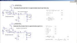
Some of those in this thread have focused like a laser on the fact that ic = gm x vbe. This has perhaps led to ignoring another fact: ic = alpha ie, where alpha is a dimensionless parameter slightly less than 1.
Fortunately, there exist well-accepted small signal transistor models that reflect each of these principles. In the attachment, nodal current equations of closed-loop CFA schematics are written by inspection and then solved for ic. The results are reproduced here:

Note how difficult it is to simplify the coefficient of vbe in comparison to the fact the coefficient of ie is approximately 1. For this reason alone, I prefer the ie formulation. Add to that the fact that ie = ignd - io, and we can now formally mathematically confirm the extent to which input stage current is in part output stage current.
Clearly, part of output stage current feeds input stage current in a CFA, just as part of output stage voltage drives one of the inputs of the VFA input stage.
In both cases, there is a feed "back".
In a straight forward application of language, VFAs experience voltage feedback and CFAs current feedback.
If you still contest this claim, you must believe that there is a flaw in this logic. It should be easy for you to point it out.
Will you?
Some of those in this thread have focused like a laser on the fact that ic = gm x vbe. This has perhaps led to ignoring another fact: ic = alpha ie, where alpha is a dimensionless parameter slightly less than 1.
Fortunately, there exist well-accepted small signal transistor models that reflect each of these principles. In the attachment, nodal current equations of closed-loop CFA schematics are written by inspection and then solved for ic. The results are reproduced here:
Note how difficult it is to simplify the coefficient of vbe in comparison to the fact the coefficient of ie is approximately 1. For this reason alone, I prefer the ie formulation. Add to that the fact that ie = ignd - io, and we can now formally mathematically confirm the extent to which input stage current is in part output stage current.
Clearly, part of output stage current feeds input stage current in a CFA, just as part of output stage voltage drives one of the inputs of the VFA input stage.
In both cases, there is a feed "back".
In a straight forward application of language, VFAs experience voltage feedback and CFAs current feedback.
If you still contest this claim, you must believe that there is a flaw in this logic. It should be easy for you to point it out.
Will you?
Attachments
And as I said before I find it useful to look at the LT1364 schematic where we can see that the added buffer and 500R degen resistor isolate the FB network impedance and present a new, fixed OLG "gain" impedance. So I wouldn't agree that a whole lot has changed except that the "gain" impedance is fixed and constant and not depending on the FB network impedance... and that's just about the only difference of VFA vs CFA: the CFA's OLG depends on the external node impedance of the -IN, whereas in a VFA it doesn't.
Re #946 / LT1364 --- The 500 Ohm resistor is known as a series peaking R. The chosen value uplifts a slow HF roll-off and extends the -3dB Freq response . flat further.
THx-RNMarsh
Last edited:
Will you?
All,
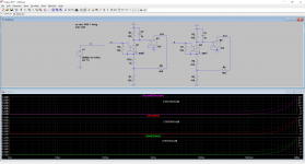
I did some simulations on a little "CFA" scheme in order to try to have the revelation of the true truth of death that kills on the nature of feedback in the "CFA".
There are 2 schemes, the only difference between them is that on the second I add a resistor between the 1st transistor emitter and the feedback network.
1) This doesn't change very much the gain which is around 20dB
2) I plot :
- the ratio of the output of each scheme
- the ratio of the emitter current on the first transistors
- the ratio of the Vbe of the first transistors.
We can read that output are not exactly the same, that is not so surprising.
The ratio of the emitter current of the first transistors is not equal to the output ratio.
The ratio of Vbe of first transistors is exactly the same as the ouput.
I am pretty sure that inexperienced beginners ignoring 3.5 billions years of audio electronics history would conclude that we are not in presence of "current feedback" but may be something else.
But you are not inexperienced beginners ?
Attachments
If it’s voltage feedback, then you should be able to raise the feedback resistor (Rf and Rg) by a a factor of 5 or 10 with little or no change in performance.
Is this the case with your model?
Is this the case with your model?
In a black-box approach the innards are totally irrelevant, aren't they? With a black-box all we need to observe is a strong dependancy of OLG vs -IN node impedance, or in other words look for non-zero current in/out of the -IN in open-loop conditions (other than bias current) with that current being "in sync" with the input differential.Interesting. For me that would be THE difference that makes a CFA a CFA.
Never heard of that term but the effect is indeed quite obvious. Effectively 500 Ohms seems a bit too low for a perfect flat (Butterworth) unity gain response but Mfgrs live off of BW specs so they opted to compromise phase margin at unity gain.Re #946 / LT1364 --- The 500 Ohm resistor is known as a series peaking R. The chosen value uplifts a slow HF roll-off and extends the -3dB Freq response . flat further.
- Home
- Amplifiers
- Solid State
- Current Feedback Amplifiers, not only a semantic problem?