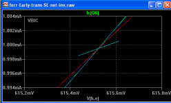
I have also Simulated the same model again with VBIC transistor models based on the info that Keantoken gave.
Results are below.
Apart from different HF behaviour I do not see that many differences.
Hans
Hopefully, some of the folks on this thread will help us get to the bottom of all of this.
We both know that I presented ic/vbe, that's obvious from the images.Hans, please discriminate between ic/vbe and gm. Even if the Early effect does not explain the phenomenon we are discussing, it does exist.
Please give me the values for gce, rbb and rb'c and I'll repeat the sims.Yes, Hybrid Pi does not explain everything, so there might be something else going on. But it is derived from the Ebers-Moll and Early equations/models. Attached is a more complete H-pi model. the text that goes along with its is:
You can forget about Ce and Cc.
Hans
We both know that I presented ic/vbe, that's obvious from the images.
No question. But can we make the distinction in the future? Because there are other discussions going on where people are questioning whether gm is changing, not just ic/vbe.
Please give me the values for gce, rbb and rb'c and I'll repeat the sims.
You can forget about Ce and Cc.
Hans
There are five resistances/conductances and only three two-terminal measurements to be made. I don't know how these values could be sim'd or measured.
The thing I found interesting is that some references state that hoe = 1/ro should be measured at constant ib (which I did) and others with constant vbe. (I wonder if it makes a difference.) Can anyone speak authoritatively about this? I think I recall Scott having something to say on the matter.
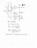
I thought you and Hans might find this interesting for whatever it is worth. It uses a Thevenin translation that in the first approximation is absent of an input network. The analysis is based upon a condition of balanced current mirrors as a means to predict the behaviour of the feedback loop. The formulas are derived from the translation as leading to several conclusions.
This predicts that an input network inserted into the current path, as to generate Vx will behave accordingly as the network causing the currents to occur. Hence in the first approximation the feedback network behaves in a specific manner as to thereafter be modified by characteristics of an input network.
The formulas also reveal that there exists a direct relationship of V Thevenin to Vout, as well as of V Ref to Vout. Hence V Ref and V Thev are related by some constant ratio. It can be realized that under circumstances whereupon an input network exists, Vin is being tracked by a virtual Thevenin buffer dynamically current limiting the amount of current passing through the Rf || Rg + Z(In-).
It is in the conceptual belief of a virtual tracking Thevenin buffer that gave rise to my earlier conclusion that the behaviour of a CFA is one of feedback current limiting.
Attachments
I thought you and Hans might find this interesting for whatever it is worth. It uses a Thevenin translation that in the first approximation is absent of an input network. The analysis is based upon a condition of balanced current mirrors as a means to predict the behaviour of the feedback loop. The formulas are derived from the translation as leading to several conclusions...
It is in the conceptual belief of a virtual tracking Thevenin buffer that gave rise to my earlier conclusion that the behaviour of a CFA is one of feedback current limiting.
Well seen, Hierfi. However, I do think it comes down to asking why the "other camp" believes that the existence of voltage feedback means that there can be no current feedback whatsoever. I think your earlier "Thevenin 1" makes a stronger point to this effect.
Hi keantoken,Here is the schematic in single ended inverted form. No Gm anomaly.
Thanks. But when I make it non-inverting input the variation is present. See attached.
Your no variation in inverting mode is a positive result to understand this effect.
I don't think asymmetry fully explains the variation for the non-inverting mode. (asymmetry is a factor but there is something more than this).
I have another run following this post with the fully complementary version with pnp and npn VBIC.
Attachments
Isn't that exactly what I did over here Current Feedback Amplifiers, not only a semantic problem?Hi keantoken,
I have another run following this post with the fully complementary version with pnp and npn VBIC.
Hans
Chris,Yes, Hybrid Pi does not explain everything, so there might be something else going on. But it is derived from the Ebers-Moll and Early equations/models. Attached is a more complete H-pi model. the text that goes along with its is:
Full hybrid-pi model
The full model introduces the virtual terminal, B', so that the base spreading resistance, rbb, (the bulk resistance between the base contact and the active region of the base under the emitter) and rb'e (representing the base current required to make up for recombination of minority carriers in the base region) can be represented separately. Ce is the diffusion capacitance representing minority carrier storage in the base. The feedback components, rb'c and Cc, are introduced to represent the Early effect.
The initial simple assumption that Ro was responsible for the growing difference between ic/vbe and gm when increasing Rload was proven to be incorrect after having nihilated current leaking into Ro with an equal current in the opposite direction. Current Feedback Amplifiers, not only a semantic problem?
From here things are getting complicated, because we have no prove at all whether this phenomena is an artefact of LTSpice or a real issue.
As long as we don't know exactly what LTSpice is doing, each model we are trying to apply can differ substantially leading to wrong conclusions.
So this elaborated Pi model can just as well send us in the wrong direction.
Maybe someone on this forum, can tell us what the real and complete model is that LTSpice is using for a transistor.
Hans
Chris,Ian, ...
You found a change of a factor of 3 rather than one of 300. The mystery is that there is any change at all! If a model's capacitance changes transistor transconductance at 1kHz by a factor of 3, there is a problem with the model, don't you agree? Again, I think that the simpler explanation is that gm as defined above is unchanged and that it is ic6/vbe6 only that changes.
... The thing I most want is for us to both agree on the correct explanation, and to be cured of any misapprehension I might have.
For me, the first step in this process would be for you to find an error in my explanation. Would you be willing to do this?
OK, no change in DC bias.
Isn't "the first step" the explanation for the change in Ic slope with respect the Vbe. So far we have:
The change of slope is visible in my previous post 2166 with a single ended version. This is a large signal simulation.
There is no change in slope if the signal is fed into the inverting input via a 1k resistor (or as a sinewave current injection of 1mA/V).
There is a difference between the VBIC an GP models with (near) identical parameters.
The VBIC parameter 'mc' changes the large signal LF gain (see below) as well as the HF part.
I don't want to try to find an error in you previous explanation; I don't understand well enough yet what is causing this anomaly.
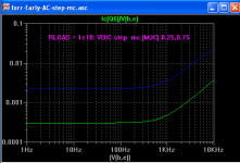
The changing capacitance question. I have plotted Ic6/Vbe6 with AC. See attached.
It is VBIC with 1e10 load and step 'mc' (MJC) from 0.25 to 0.75. Notice two things: the LF gain changes by a factor of 10, and the capacitance has changed by a factor of 10 (giving the same the HF transition frequency).
So the VBIC 'mc' parameter (for the b-c junction capacitance variation with Vbe) does appear to affect the LF gain in this circuit, not only the capacitance for HF. If 'mc' was purely a capacitance parameter then it would not affect the LF part. Mc appears to affect the DC equations (and seen in the AC plots) and it interacts with the Early effect.
@Hans. I did see your sim. Good work. Thanks.
Cheers,
Attachments
Last edited:
Hans,
You could ask Helmut Sennewald on the LTspice users forum on Yahoo. He was one of the guys (the main guy if my info is correct) that coded LTspice. He’s pretty clued up on the modeling side as well.
Are there any differences in the error reports between the two resistor values? I’m wondering if the circuit is struggling to converge, so spice iterates before solving, and maybe you get an error like this?
Last edited:
Hans,
You could ask Helmut Sennewald on the LTspice users forum on Yahoo. He was one of the guys (the main guy if my info is correct) that coded LTspice.
Not sure about that, but we had our own group that built an in-house SPICE (one of the first to include T, along with I, and V) as well as converting it to an interactive scriptable environment (no more virtual punch cards littering the schematic). The latest complementary processes were all based on Mextram models and real silicon matched the sims to almost uncanny accuracy. This current discussion around ro still baffles me.
Last edited:
Hi Scott,
You’ll be closer to the facts than me on that - just what I was told a few years ago.
I would think ro would be swamped by the load impedance on Tz at HF, but I am not as close to the detail as Chris, Hans and Ian on that, so I will defer to them on that.
You’ll be closer to the facts than me on that - just what I was told a few years ago.
I would think ro would be swamped by the load impedance on Tz at HF, but I am not as close to the detail as Chris, Hans and Ian on that, so I will defer to them on that.
Hans
Chris,
OK, no change in DC bias...
Cheers,
I did some sims that started this whole thing. Ebers-Moll/Early and the low frequency Hybrid Pi model both support the idea that the transconductive and Early resistive effect combine in a subtractive manner similar to how the original sim performed. You can see that from the equation, and you don't have to put the Hybrid PI in a loop to see the subtractive effect. I also did some bench measurements which don't prove the original theory, but seem to conform with it.
However, you both have gone well beyond what I did in sims, and the sim results don't point at Early.
If you don't mind, I'd be happy to step back at this point and see what conclusions you and others come up with.
How strange it will be if it turns out that the Spice models reflect a real world effect that E-M/Early and Hybrid-Pi ignore.
Hi Scott,
You’ll be closer to the facts than me on that - just what I was told a few years ago.
That could very well be, I was only familiar with things from a long time ago. As you can imagine the merger got lots of bodies flying. 😉
How strange it will be if it turns out that the Spice models reflect a real world effect that E-M/Early and Hybrid-Pi ignore.
I could see Hybrid-Pi since it is not very physics based, but in general this discussion does not happen with the folks designing all the IC's, you'll have to sort it out among yourselves.
Hi Scott,
You’ll be closer to the facts than me on that - just what I was told a few years ago.
I would think ro would be swamped by the load impedance on Tz at HF, but I am not as close to the detail as Chris, Hans and Ian on that, so I will defer to them on that.
Just to be clear in case it's not, the discussion is about what's happening with the input transistors, (not the ones driving the Tz node) under high loop gain (low frequency) operation.
I have also Simulated the same model again with VBIC transistor models based on the info that Keantoken gave.
Results are below.
Apart from different HF behaviour I do not see that many differences.
Hans
For those not following completely, this explains everything. Notice Hans has replaced the entire Diamond follower with the VBIC transistor. Since the Early effects cancel in a Diamond follower, changing one transistor to another model will cause a mismatch. The resulting transverse currents become a confounder. Therefore in an honest comparison the whole Diamond follower needs to use the new models.
Also notice that the simulation reports much lower than the 37mS we predict for Gm just based on Ic. This is because as the current load disappears, the voltage gain of a transistor does not go infinite. Early effect limits it to a certain value.
In a non-inverting amplifier the input voltage acts as a voltage load, since a transistor has no knowledge of ground. It just knows that Vce is changing. Therefore change to inverting input and the Gm behaves as predicted.
Well seen, Hierfi. However, I do think it comes down to asking why the "other camp" believes that the existence of voltage feedback means that there can be no current feedback whatsoever. I think your earlier "Thevenin 1" makes a stronger point to this effect.
Thanks Paul... and yes I think so. It was from an earlier post by someone (this could have been you) that suggested that input network behaviour wasn't entirely or necessarily responsible for the nature of the feedback. It was for this reason that I wanted to examine feedback in absence of an input network.
The datasheet presents the TPA6210 as CFA . What makes this power op amp to be so , where it has standard VFA applications?
That could very well be, I was only familiar with things from a long time ago. As you can imagine the merger got lots of bodies flying. 😉
Since the Berkeley original version, Spice uses by default 4 BJT models: DC, Transient, AC, AC noise.
In many implementations, DC and Transient models are the same (Gummel Poon) while the AC and AC noise models are both based on the hybrid Pi model, with the notable difference the AC noise model has Johnson noise current sources attached to all internal real part of the impedances, with the notable exception of the gbc - that cannot be justified based on the device physics (a gbc conductance doesn’t physically exist).
The Early effect in the hybrid Pi model for AC and AC noise models is defined as VAF/Ic, where Ic is the bias current, VAF is the forward Early voltage, and is constant and frequency independent, so I personally keep missing what you are struggling here with. In fact, all AC and AC noise BJT model parameters are constant, frequency independent, and determined at the DC simulation step. The only frequency dependent elements in an AC simulation are the Cbe and Cbc impedances.
- Home
- Amplifiers
- Solid State
- Current Feedback Amplifiers, not only a semantic problem?