If you like, yes, that is the case. See appendix.The so called FFWD resistance should be treated the other way around, that is, as some NFB return path resistance.
I am already looking forward to these results, they could finally close the Quad405 case. It is possible that with a little more bias (without having to carry out correct adjustments in production, because that's what it's all about - reducing employee costs) and an optimized compensation scheme, better technical data can be achieved than with the so-called CurrentDumper principle and the strange bridge, which then is or would no longer be a bridge at all ..!I ll do a sim with the same schematic + TMC later, so FFWD + TMC and also only TMC at same (half) class C Iq.
Bye,
HBt.
Psst
It's all in the loop.
😎
take a ☕
Attachments
The impedance is computed in frequency domain with an AC source with a 1R resistance in serial for conveniance,
for a time domain computation a voltage generator at a given or sweeping frequency with a 1R + big cap in serial,
in both case this apply to low impedance nodes as the resistance has to be set accordingly to the tested node Z.
The inner amp of the Quad has 110-114dB OLG, so there s 98-102dB NFB distributed between the miller loop and the GNFB,
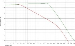
the curves below are with and without the compensation.
And thank you, i always have a coffee at hand, i used a TOP3 transistor fixed below a 3cm thick 4 x 4cm alu block
to keep the inox 0.25L glass always hot.😉
for a time domain computation a voltage generator at a given or sweeping frequency with a 1R + big cap in serial,
in both case this apply to low impedance nodes as the resistance has to be set accordingly to the tested node Z.
The inner amp of the Quad has 110-114dB OLG, so there s 98-102dB NFB distributed between the miller loop and the GNFB,
the curves below are with and without the compensation.
And thank you, i always have a coffee at hand, i used a TOP3 transistor fixed below a 3cm thick 4 x 4cm alu block
to keep the inox 0.25L glass always hot.😉
Attachments
Last edited:
My God,
the dinosaur will haunt me in my sleep tonight if we solve the puzzle completely and comprehensibly any time soon.
At some point, in the course of the time function (let's not make it any more “complex” ... ), the VAS takes its magical 47Ohm resistor out of the directly recognizable gnfb loop, at least practically speaking - you could consider these time periods as those in which a normal class B quasi-complementary push-pull output stage is present, we could also think about how to convert two strangely kinked transfer functions into a single and linear one - draw a bold line parallel to the X-axis (the level) in the wingspread diagram..?!
Jesus,
you're quick wahab.
😉
Sorry,
I must ask you:
what is green, and what is red ---> respectively how red becomes green (I know it is the difference between the methods of compensation).
Green ist great.
I must ask you:
what is green, and what is red ---> respectively how red becomes green (I know it is the difference between the methods of compensation).
Green ist great.

Apart from that, we can now do a bit of math with your figures.
1) 78dB + 11.5dB = 89dB OLG
2) 57.5dB + 11.5dB = 69dB OLG
My calculation values, quasi back-calculated from your resistance values, not simply copied, but calculated by hand.
How does this fit in with your last / penultimate simulation?The impedance at the QC output is 32 uR at 1kHz and 340 uR at 20kHz.
When OL the numbers are 250-260 mR at both frequencies.
Hence the total (G?)NFB around the OS is 78dB and 57dB respectively, 57dB GNFB at 20kHz is unheard of in usual miller
compensated amps.
tpc.
ok.Red is with the 120pF cap and green with the cap removed.
ok - agreedGreen minus red = local NFB inside the miller loop, FI 60dB local NFB at 10kHz.
thats explain itRed minus 12dB = GNFB.
whats up with the ri in the two cases now ?Load is of course 8R in all cases.
#
Somehow we still need the missing and resounding evidence for the success of the CurrentDumper principle.
For the red track, the fu (-3dB) is slightly greater than 100kHz. An 50dB minus 20dB is 30dB plus 11.5dB ---> the amount is not better 41.5dB, result in THD reduction only two shifts left -looking at f_signal = 20kHz!
Last edited:
Only the GNFB reduce the output impedances (and THD) comparatively to the OL output impedance, that s straitfoward,
the miller loop local NFB logicaly reduce only the VAS output Z and THD, unless of course that the OS is enclosed in this loop,
in wich case it will also benefit from an additional local NFB that will reduce its output Z and THD with the GNFB
added on top.
Edit : what is ri..?
the miller loop local NFB logicaly reduce only the VAS output Z and THD, unless of course that the OS is enclosed in this loop,
in wich case it will also benefit from an additional local NFB that will reduce its output Z and THD with the GNFB
added on top.
Edit : what is ri..?
The term ri means "dynamischer Innenwiderstand der Quelle", in other words, the AC output resistance of the amplifier.
Unfortunately, the deduction now says the following:For the red track, the fu (-3dB) is slightly greater than 100kHz. An 50dB minus 20dB is 30dB plus 11.5dB ---> the amount is not better 41.5dB, result in THD reduction only two shifts left -looking at f_signal = 20kHz!
The gnfb alone cannot be responsible for the super good THD and the THD curve. @jxdking had already established this at the very beginning of the thread.
Maybe a paradox!
But repeating once again, when the dumpers are in play, everything is in the loop.
Psst
my wife calls me to order, I have to finish and hang up.

Psst
my wife calls me to order, I have to finish and hang up.
The gain at high frequency is a little higher actually, the two 330pF caps are to be also removed,
as for the THD being too good for 100dB total NFB that s just not true as a blameless has better numbers
with a comparable OLG and despite quite higher CLG.
Also the miller loop NFB provided to the OS doesnt appear in these curves by the definition, that s the same with
TMC, you cant deduct the added NFB out of the OLG and CLG curves, this was abundantly discussed here 15 years ago
and i wont reinvent the wheel, there s enough old threads on the subject.
And I don't want to give a lecture, so I'll be brief - without providing evidence or explanations, I'll just tell it like it is.and i wont reinvent the wheel, there s enough old threads on the subject.
#
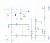
For me, the Amplifier behavior is obvious. Nevertheless, I will feed MC12 (with exactly your model / BJT recommendations), and maybe post a few simulation results - commented or uncommented, I don't know yet.
Attachments
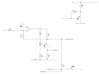
open loop - offene Schleife - without TIAN-Probe, but with C6=120pF

open loop - offene Schleife - without TIAN-Probe, and also without C6

open loop - offene Schleife - without TIAN-Probe, and also without C6
- Home
- Amplifiers
- Solid State
- Current Dumping with OPAMP