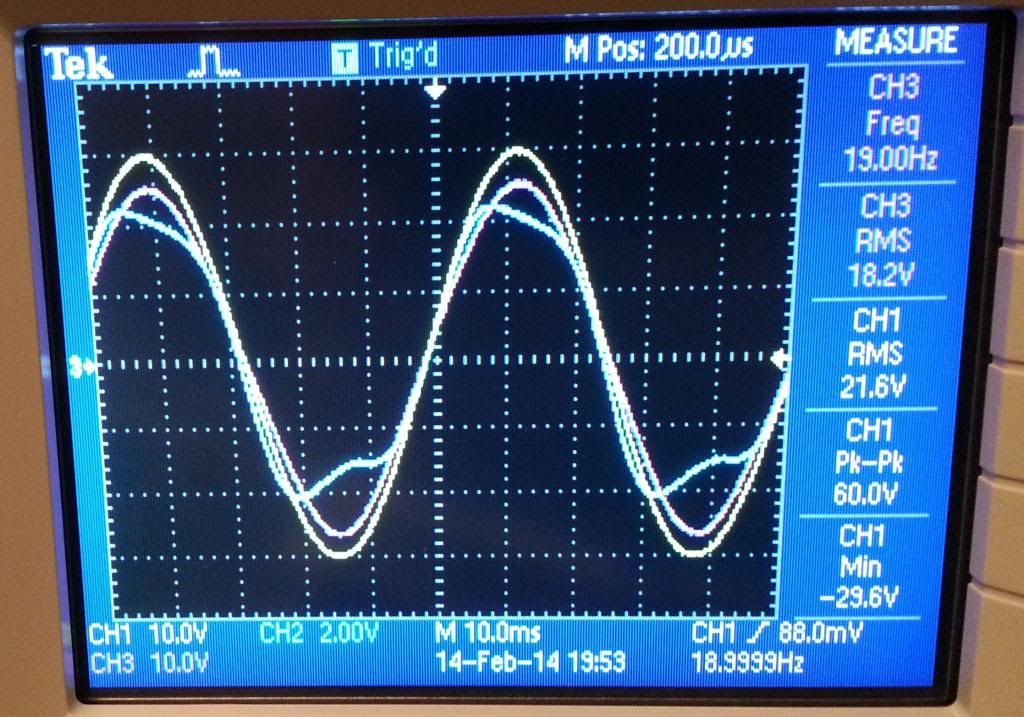
Woofer, this is a very high level 36Vrms at resonance 😱
How much is the cone moving (+/- ? mm) ?
Can you do another scope pic with the cone moving at Xmax and another at 1/2 Xmax?
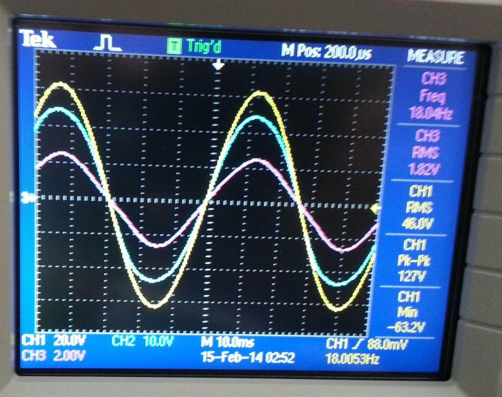
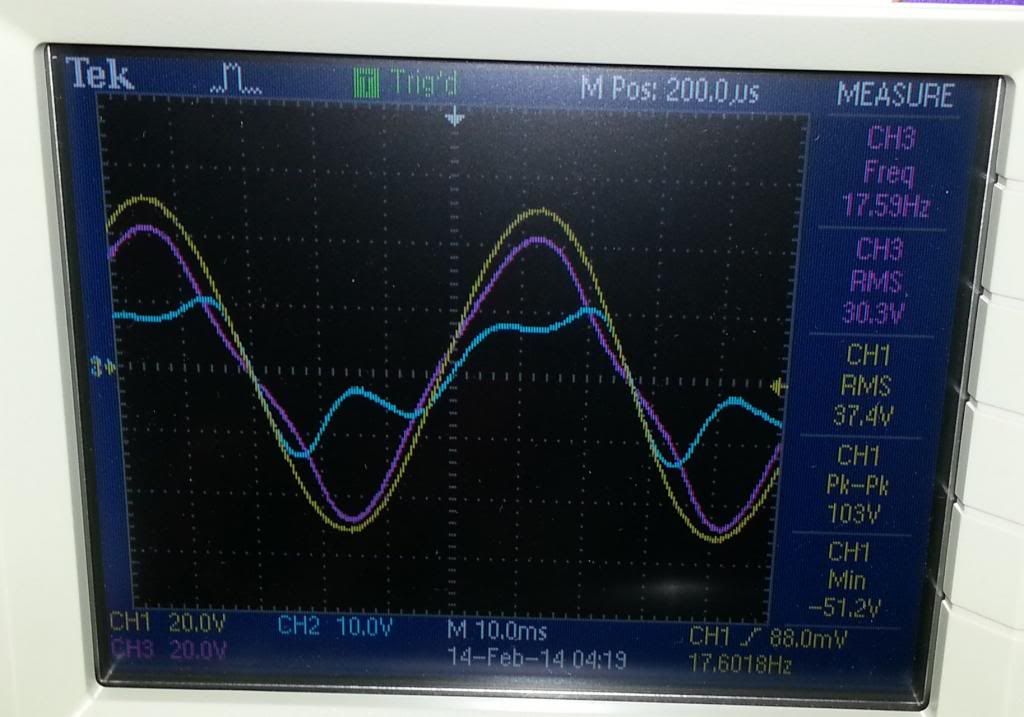
The scope shot posted at 36V is just about Xmax; 3 to 4 inches p-p. The following scope shot is about 1/2 of that drive, 1.5 amps at resonance:
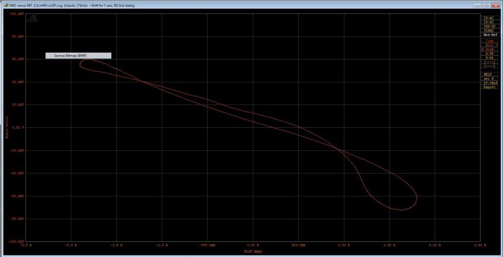
Using the WTPro X-Y mode I plotted a suspended mic above the woofer vs current in the voice coil. The slope of the plot should be proportional to BL. Here it is
> isn't Nelson using an output xformer?
Maybe ?? I sorta doubt it, but don't know.
Anyways my circuit (inspired by the 'square law amplifier'
in your volume 2) is ~ 80 Ohm out without any network
Maybe ?? I sorta doubt it, but don't know.
Anyways my circuit (inspired by the 'square law amplifier'
in your volume 2) is ~ 80 Ohm out without any network
Woofertester --- I never got back with you from last year --- took off for Asia.... but did you find an amp for your project -- mine are 900W/4 class AB balanced/bridge amps at <.01% mono amps.... dont know what the 1% power output is. What needs to be done to use them for a current-drive amp or?
These are the same amps I designed for Dave Wilson's subs a few years back and the ones I was planning to use with the TC-Sounds (if I dont use a gang of QUADS instead). .
-Richard
I found a thoroughly obscure, one-of-a-kind amp that is exactly what I need initially. It is voltage in, current out, 4A RMS at 48V RMS. It has a +/- offset control. It is intended for industrial use and is a custom order product. I ordered one and am having it modified a small amount for the gain I need to bolt up to the WTPro.
If it works but is still underpowered at 4A I will want a bigger, beefier version which could use your amp as the heart. Is the monoblock bridged? We can't use a bridged amp. The current measurement shunt in the WTPro has to be grounded at the amp output Lo/Ground.
Woofertester,
That must have been quite a woofer, when you can feed 100 Watts into at Fs without mechanical destruction.
About your measurement: I don't think the distortion you see in the purple curve is just caused by BL non-linearity. The reason is that there will be a phase shift between the yellow and the purple curves, not shown in your measurement. At the same time, in a dual voice coil, the driven coil and the measurement coil will be working as the windings of a transformer. You will pick this up in measurements, certainly if your measuring instrument has a high input impedance.
In other words, you may be adding two out of phase sinoids with your measurement, and this will give you the kind of curve my eye seems to detect in the purple curve.
Therefore, it would be interesting to see the same measurement with the measurement coil being terminated with a low R.
1st Pass Current Drive
In case anyone isn't aware, Nelson's article is, IMHO, the best treatment of what Merilainen only obfuscates.
Pass on Current Drive http://www.firstwatt.com/pdf/art_cs_amps.pdf
In REALLY pre-Jurassic times, I played with a couple of Lowther PM6 units and really liked them.
Note the amount of fudging needed to get good results. The article also has clues on how to design drive units for good Current Drive performance. There still isn't a good method for this moving coil Black Magic without Unobtainium.
There IS a good method for Current Drive electrostatics.
Last edited:
That's a hell of a bass unit with 4" p-p excursion. What is it?The scope shot posted at 36V is just about Xmax; 3 to 4 inches p-p. The following scope shot is about 1/2 of that drive, 1.5 amps at resonance:
Is the new scope pic showing about 1.5-2" p-p excursion?
Which of the 3 curves on the scope is the wonky one? The other 2 are sorta clean.
Vacuphile, if you short the measurement coil, you apply EXACTLY the same amount of Electromagnetic Damping as though you'd used Voltage Drive on the amp.
Last edited:
Alas, I'm still in the 20th century with my DOS compiler which severely limits the size of data I can process .. and worse, machines that can run DOS will soon be extinct.
DOS runs fine in Sun's Virtual Box on a Mac (probably in Parallels & Fusion as well)
dave
Sure Kgrlee, and it would be a perfect amp at that. Please reread my post. The point is that if you want to exclude the transformer effect between the two coils, you need to measure with a low terminating R.
The reason is obvious. The back EMF signal is robust, that is, it can deliver sizeable current. The transformer effect between the two coils is not rubust. If terminated with a high Z, the voltage will be considerable. However, this will collaps at a lower R, because it can only deliver a very low current. In other words, with a low R terminating the speaker, you will see the back EMF with less contamination by the out of phase transformer effect.
The reason is obvious. The back EMF signal is robust, that is, it can deliver sizeable current. The transformer effect between the two coils is not rubust. If terminated with a high Z, the voltage will be considerable. However, this will collaps at a lower R, because it can only deliver a very low current. In other words, with a low R terminating the speaker, you will see the back EMF with less contamination by the out of phase transformer effect.
> and worse, machines that can run DOS will soon be extinct.
Not really, because the new ones use DOS to access the Flash BIOS
Not really, because the new ones use DOS to access the Flash BIOS
That's a hell of a bass unit with 4" p-p excursion. What is it?
Is the new scope pic showing about 1.5-2" p-p excursion?
Which of the 3 curves on the scope is the wonky one? The other 2 are sorta clean.
Vacuphile, if you short the measurement coil, you apply EXACTLY the same amount of Electromagnetic Damping as though you'd used Voltage Drive on the amp.
The woofer is a Tantric Sounds HD 12".
Tantric SubWoofers
It was made for me for the purposes of creating a reliable way to test BL at Xmax as well as measure excursion reliably.
The new scope shot is 1.5 amps RMS. It is about 1/2 of Xmax. Probably a bit less.
The wonky curve is the current in the driven voice coil. At 37.4 V rms drive the current in the voice coil is about equal parts fundamental, H2 and H3.
Sure Kgrlee, and it would be a perfect amp at that. Please reread my post. The point is that if you want to exclude the transformer effect between the two coils, you need to measure with a low terminating R.
The reason is obvious. The back EMF signal is robust, that is, it can deliver sizeable current. The transformer effect between the two coils is not rubust. If terminated with a high Z, the voltage will be considerable. However, this will collaps at a lower R, because it can only deliver a very low current. In other words, with a low R terminating the speaker, you will see the back EMF with less contamination by the out of phase transformer effect.
Interesting experiment and results.
One coil is loaded with a 0.25 ohm Caddock non inductive power resistor.
Amp is turned up to maximum. Freq is adjusted for Fs. Results below
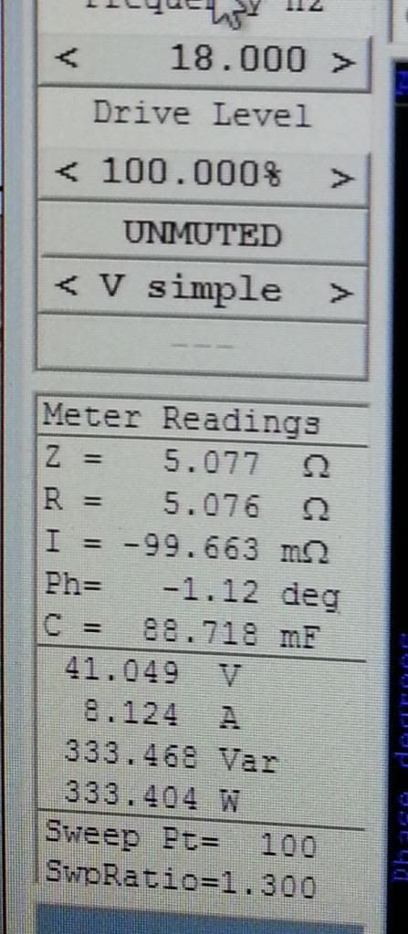
Zmax drops from 12 ohms to 5 ohms. Onset of clipping is over 300 watts. I can get to 350 with careful adjustments. Check out the current into the speaker, 8 amps rms.
Scope shows that current distortion is essentially gone.
Power into resistors is 13 watts. The coil is 2.2 ohms-ish. Power developed in the shorted coil would be 116 watts.
Excursion is high but not at Xmax.
Keith, very interesting! I'll give you a call.
Not Keith, but we work together.
There IS a good method for Current Drive electrostatics.
What is the good method?
Woofertester - My TC-Sounds are DVC also... as are many other woofers.....so this is very interesting to me.
The mono-amp might be used with a mod or two for your needs..... an awful lot of current capability.... 10+A continuous. The darn things are really big and heavy, too. You might want to use a 'digital' amp instead.
-THxRNMarsh
Last edited:
What is the good method?
Woofertester - My TC-Sounds are DVC also... as are many other woofers.....so this is very interesting to me.
The mono-amp might be used with a mod or two for your needs..... an awful lot of current capability.... 10+A continuous. The darn things are really big and heavy, too. You might want to use a 'digital' amp instead.
-THxRNMarsh
Is the monoblock bridged? I have thought about a digital amp but I think that they are not ground referenced. Most car audio amps cannot be used with the WTPro for this reason.
Here are the results for the DVC woofer. You can easily replicate these with a WT2.
--------------------------------------------------------------------------
Two coils in parallel
Re = 1.4688 ohms
Fs = 31.7038 Hz
Zmax = 16.3090 ohms
Qes = 0.8237
Qms = 8.3224
Qts = 0.7495
Le = 0.9176 mH (at 1 kHz)
Diam = 254.0000 mm ( 10.0000 in )
Sd = 50670.7504 mm^2( 78.5398 in^2)
Vas = 22.4941 L ( 0.7944 ft^3)
BL = 12.0478 N/A
Mms = 408.6299 g
Cms = 61.6721 uM/N
Kms = 16214.7891 N/M
Rms = 9.7808 R mechanical
Efficiency = 0.0818 %
Sensitivity= 81.1439 dB @1W/1m
Sensitivity= 88.5052 dB @2.83Vrms/1m
Krm = 4.609E-03 ohms Freq dependent resistance
Erm = 735.363E-03 Rem=Krm*(2*pi*f)^Erm
Kxm = 23.003E-03 Henries Freq dependent reactance
Exm = 630.305E-03 Xem=Kxm*(2*pi*f)^Exm
------------------------------------------------------------------------
One coil only
Re = 1.9505 ohms
Fs = 31.6944 Hz
Zmax = 16.7358 ohms
Qes = 1.1031
Qms = 8.3618
Qts = 0.9745
Le = 0.9352 mH (at 1 kHz)
Diam = 254.0000 mm ( 10.0000 in )
Sd = 50670.7504 mm^2( 78.5398 in^2)
Vas = 22.3070 L ( 0.7878 ft^3)
BL = 12.0491 N/A
Mms = 412.3008 g
Cms = 61.1592 uM/N
Kms = 16350.7607 N/M
Rms = 9.8192 R mechanical
Efficiency = 0.0605 %
Sensitivity= 79.8353 dB @1W/1m
Sensitivity= 85.9648 dB @2.83Vrms/1m
Krm = 4.705E-03 ohms Freq dependent resistance
Erm = 732.042E-03 Rem=Krm*(2*pi*f)^Erm
Kxm = 22.991E-03 Henries Freq dependent reactance
Exm = 631.155E-03 Xem=Kxm*(2*pi*f)^Exm
----------------------------------------------------------------------
One coil driven, the other coil shorted
Re = 2.3017 ohms
Fs = 31.9281 Hz
Zmax = 4.8236 ohms
Qes = 1.3462
Qms = 1.4750
Qts = 0.7038
Le = 0.1443 mH (at 1 kHz)
Diam = 254.0000 mm ( 10.0000 in )
Sd = 50670.7504 mm^2( 78.5398 in^2)
Vas = 18.9477 L ( 0.6691 ft^3)
BL = 12.8086 N/A
Mms = 478.3186 g
Cms = 51.9491 uM/N
Kms = 19249.6289 N/M
Rms = 65.0543 R mechanical
Efficiency = 0.0430 %
Sensitivity= 78.3572 dB @1W/1m
Sensitivity= 83.7677 dB @2.83Vrms/1m
Krm = 43.578E-03 ohms Freq dependent resistance
Erm = 368.270E-03 Rem=Krm*(2*pi*f)^Erm
Kxm = 155.161E-03 Henries Freq dependent reactance
Exm = 301.019E-03 Xem=Kxm*(2*pi*f)^Exm
Shorting one coil makes the effective inductance go way down. This configuration has way less current distortion at high excursion. I will carefully compare this config to a normal config driven by a current source amp. I am wondering if the shorted coil acts as a shorting ring that some manufacturers build in to a speaker.
> I am wondering if the shorted coil
> acts as a shorting ring
> that some manufacturers
> build in to a speaker.
Mega 🙂
Anyways, obviously, ........
You could drive 1 coil of a DVC driver ...
And experiment with loading the other
> acts as a shorting ring
> that some manufacturers
> build in to a speaker.
Mega 🙂
Anyways, obviously, ........
You could drive 1 coil of a DVC driver ...
And experiment with loading the other
Last edited:
There IS a good method for Current Drive electrostatics.
It's in Peter Walker's New Developments in Electrostatic LoudspeakersWhat is the good method?
He shows a direct relationship between Current and Acoustic Response. But he doesn't take full advantage of this. Most of the Current flows into the resistor terminating his Delay Line.
If you make ALL the current flow through the capacitor plates, an electrostatic the size of the ELS63 would have 94dB/2.83V @ 1m sensitivity while presenting 8R resistance to the amp.
I've done a lot of theoretical work on this but never built an electrostatic. I need to talk to a true transformer guru. Talking to Peter Walker & Baxandall comes up with a host of other caveats too .. but not insurmountable.
________________
This is where Merilainen & other pseudo gurus come apart. They are so obsessed with the transfer function to the voice coil, the cone, diaphragm bla bla that they forget the ONLY one which matters is the transfer function from voltage or current input .. to pressure/velocity of the air at the listening position.
We are only interested in the intermediate steps if they improve the final transfer function.
That's why measuring Acoustic Distortion is important.
Difference between the applied voltage and the sensed voltage
Firstly, for expediency, please let me refer to the two voltages of the Dual-Voice-Coil (DVC) driver as follows:
My questions are:
Regarding Question 2 (i.e. the distortion in the sensed voltage Vs), I notice the following:
When the drive voltage Vd is reduced (so as to produce ~ half of the maximum excursion, as I understand from Woofertester's message #181), the distortion in the sensed voltage Vs disappears almost totally. Please see the purple trace in the scope picture below (from message #181).
Nevertheless, as evident in the picture above, there still remains a voltage difference between Vd and Vs (which are now fully in phase).
Besides, as can be seen from Woofertester's message #191 quoted below,
when the sense-coil is loaded with a 0.25 ohm non-inductive resistor, the magnitude of Vs reduces considerably (as expected, since the sense-coil is effectively almost short-circuited). In this case, the sensed voltage Vs (purple trace) is not distorted and is still in phase with the applied voltage Vd (yellow trace). Obviously, shorting of the sense-coil exerts a large amount of damping on the motion of the (total) voice-coil in this voltage-driven case.
I am not bothered too much about this particular case (presented in message #191). Because I am trying to understand the relationship (if any) between the voltage difference (Vd - Vs) and the current (particularly its waveform) flowing in the driven coil (blue traces in messages # 168, 181 and 191).
Thanks for reading this far.
In the scope shot below, yellow is the voltage driven to one coil of a DVC woofer. Blue is the current in the driven coil. Purple is the open circuit voltage of the un-driven second voice coil.
Firstly, for expediency, please let me refer to the two voltages of the Dual-Voice-Coil (DVC) driver as follows:
Vd (drive voltage) = the voltage applied to the driven coil (yellow trace in the scope picture above)
Vs (sensed voltage) = the voltage measured from the open-circuit (unloaded/undriven) second coil (purple trace above).
Vs (sensed voltage) = the voltage measured from the open-circuit (unloaded/undriven) second coil (purple trace above).
My questions are:
Q1) What or why is the difference between Vd and Vs? In other words, what causes the voltage difference Vd-Vs? Or, what does this voltage difference represent?
Q2) The sensed voltage Vs (purple trace - the voltage measured from the unloaded second coil) looks somewhat distorted. What is the cause of this distortion in Vs?
Q2) The sensed voltage Vs (purple trace - the voltage measured from the unloaded second coil) looks somewhat distorted. What is the cause of this distortion in Vs?
[Any comments towards answering these questions will help improve my understanding of the present topic: current-drive of loudspeakers. Please note that I am not an expert in audio or loudspeakers, and I am still reading about "current-drive" albeit in bits and pieces, if or when I find some - the always elusive - 'spare-time'.]
Regarding Question 2 (i.e. the distortion in the sensed voltage Vs), I notice the following:
When the drive voltage Vd is reduced (so as to produce ~ half of the maximum excursion, as I understand from Woofertester's message #181), the distortion in the sensed voltage Vs disappears almost totally. Please see the purple trace in the scope picture below (from message #181).
The scope shot posted at 36V is just about Xmax; 3 to 4 inches p-p. The following scope shot is about 1/2 of that drive, 1.5 amps at resonance:
Nevertheless, as evident in the picture above, there still remains a voltage difference between Vd and Vs (which are now fully in phase).
Besides, as can be seen from Woofertester's message #191 quoted below,
One coil is loaded with a 0.25 ohm Caddock non inductive power resistor.
Amp is turned up to maximum. Freq is adjusted for Fs.
Scope shows that current distortion is essentially gone.
Power developed in the shorted coil would be 116 watts. .
when the sense-coil is loaded with a 0.25 ohm non-inductive resistor, the magnitude of Vs reduces considerably (as expected, since the sense-coil is effectively almost short-circuited). In this case, the sensed voltage Vs (purple trace) is not distorted and is still in phase with the applied voltage Vd (yellow trace). Obviously, shorting of the sense-coil exerts a large amount of damping on the motion of the (total) voice-coil in this voltage-driven case.
I am not bothered too much about this particular case (presented in message #191). Because I am trying to understand the relationship (if any) between the voltage difference (Vd - Vs) and the current (particularly its waveform) flowing in the driven coil (blue traces in messages # 168, 181 and 191).
Thanks for reading this far.
Last edited:
Firstly, for expediency, please let me refer to the two voltages of the Dual-Voice-Coil (DVC) driver as follows:Vd (drive voltage) = the voltage applied to the driven coil (yellow trace in the scope picture above)My questions are:
Vs (sensed voltage) = the voltage measured from the open-circuit (unloaded/undriven) second coil (purple trace above).Q1) What or why is the difference between Vd and Vs? In other words, what causes the voltage difference Vd-Vs? Or, what does this voltage difference represent?
Vs is the back emf produced by the open coil #2. This voltage equals BL times cone velocity.
Q2) The sensed voltage Vs (purple trace - the voltage measured from the unloaded second coil) looks somewhat distorted. What is the cause of this distortion in Vs?
As stated above, this voltage is BL times cone velocity. BL is non-linear. The suspension is non-linear. So, the cone velocity is going to be nonlinear driving a non-linear BL in the reverse direction.
[Any comments towards answering these questions will help improve my understanding of the present topic: current-drive of loudspeakers. Please note that I am not an expert in audio or loudspeakers, and I am still reading about "current-drive" albeit in bits and pieces, if or when I find some - the always elusive - 'spare-time'.]Regarding Question 2 (i.e. the distortion in the sensed voltage Vs), I notice the following:
When the drive voltage Vd is reduced (so as to produce ~ half of the maximum excursion, as I understand from Woofertester's message #181), the distortion in the sensed voltage Vs disappears almost totally. Please see the purple trace in the scope picture below (from message #181).
I suspect that the non-itineraries are much smaller than at Xmax.
Nevertheless, as evident in the picture above, there still remains a voltage difference between Vd and Vs (which are now fully in phase).
Besides, as can be seen from Woofertester's message #191 quoted below,
when the sense-coil is loaded with a 0.25 ohm non-inductive resistor, the magnitude of Vs reduces considerably (as expected, since the sense-coil is effectively almost short-circuited). In this case, the sensed voltage Vs (purple trace) is not distorted and is still in phase with the applied voltage Vd (yellow trace). Obviously, shorting of the sense-coil exerts a large amount of damping on the motion of the (total) voice-coil in this voltage-driven case.
I am not bothered too much about this particular case (presented in message #191). Because I am trying to understand the relationship (if any) between the voltage difference (Vd - Vs) and the current (particularly its waveform) flowing in the driven coil (blue traces in messages # 168, 181 and 191).
Thanks for reading this far.
Pure current drive will make the current waveform perfect. It will not correct the BL non-linearity nor the suspension non-linearity. What current drive will do is present an open circuit to the back emf. This should reduce distortion in the acoustic output compared to voltage drive. I have not made this comparison yet. I am awaiting delivery of a 200-watt current drive amp. It will produce 4A RMS at 48 V RMS. This should take my monster woofer to Xmax or very close to Xmax with a perfect current waveform.
Many thanks for your rapid reply.
I agree with your comments emboldened above.
However, I disagree with your comment:
My understanding is that Vs (purple traces in the scope pictures) represents a combination of both motional back-EMF voltage and the voltage induced in the second (sense) coil by the current flowing in the first coil due to the transformer action (i.e. the magnetic coupling) between the two coils. In other words, the sensed voltage Vs is NOT equal to the motional back-EMF.
If my understanding above is correct, your comment does not properly answer my question 1 (what is the difference, why is there a difference, between Vd and Vs?)
As a consequence of this disagreement, I also disagree with your comment below as an answer to my question 2:
(What you are stating above may be correct but, I think, is not the full or correct answer to my question 2.)
I understand that, in the voltage-driven case that we are discussing with an unloaded/undriven second sense-coil, the current in the first drive-coil does inevitably contain distortion (as evident in the scope shots). Likewise, the motional back-emf portion of the voltage induced in the second sense-coil also contains distortion (owing to nonlinear Blv). The combination of these two should result in a highly distorted waveform for Vs, the voltage induced in the second sense-coil. However, such distortion is almost invisible in all the purple (Vs) traces in your scope shots (except for a tiny bit in the first scope shot). WHY?
I agree with your last comment:
However, this still does not answer the question "WHY?" at the end of the paragraph above. If we look at your second scope shot (below):
the current in the drive-coil (blue trace) is still highly distorted (although not so much as in the maximum-excursion case). Nevertheless, the sensed voltage Vs (purple trace) has quite an undistorted waveform. WHY? Isn't there the transformer action, i.e. mutual coupling, between the two coils? How come does the highly-distorted current in the driven coil NOT affect the voltage induced in the second sense-coil?
Besides, the magnitude difference between the drive voltage Vd (yellow trace) and the sensed voltage Vs (purple trace) seen in the scope shots still remains unexplained.
Thank you for your attention.
Pure current drive will make the current waveform perfect. It will not correct the BL non-linearity nor the suspension non-linearity. What current drive will do is present an open circuit to the back emf. This should reduce distortion in the acoustic output compared to voltage drive. I have not made this comparison yet. I am awaiting delivery of a 200-watt current drive amp. It will produce 4A RMS at 48 V RMS. This should take my monster woofer to Xmax or very close to Xmax with a perfect current waveform.
I agree with your comments emboldened above.
However, I disagree with your comment:
Vs is the back emf produced by the open coil #2. This voltage equals BL times cone velocity.
My understanding is that Vs (purple traces in the scope pictures) represents a combination of both motional back-EMF voltage and the voltage induced in the second (sense) coil by the current flowing in the first coil due to the transformer action (i.e. the magnetic coupling) between the two coils. In other words, the sensed voltage Vs is NOT equal to the motional back-EMF.
If my understanding above is correct, your comment does not properly answer my question 1 (what is the difference, why is there a difference, between Vd and Vs?)
As a consequence of this disagreement, I also disagree with your comment below as an answer to my question 2:
As stated above, this voltage is BL times cone velocity. BL is non-linear. The suspension is non-linear. So, the cone velocity is going to be nonlinear driving a non-linear BL in the reverse direction.
(What you are stating above may be correct but, I think, is not the full or correct answer to my question 2.)
I understand that, in the voltage-driven case that we are discussing with an unloaded/undriven second sense-coil, the current in the first drive-coil does inevitably contain distortion (as evident in the scope shots). Likewise, the motional back-emf portion of the voltage induced in the second sense-coil also contains distortion (owing to nonlinear Blv). The combination of these two should result in a highly distorted waveform for Vs, the voltage induced in the second sense-coil. However, such distortion is almost invisible in all the purple (Vs) traces in your scope shots (except for a tiny bit in the first scope shot). WHY?
I agree with your last comment:
I suspect that the non-itineraries are much smaller than at Xmax.
However, this still does not answer the question "WHY?" at the end of the paragraph above. If we look at your second scope shot (below):
The following scope shot is about 1/2 of that drive, 1.5 amps at resonance:
the current in the drive-coil (blue trace) is still highly distorted (although not so much as in the maximum-excursion case). Nevertheless, the sensed voltage Vs (purple trace) has quite an undistorted waveform. WHY? Isn't there the transformer action, i.e. mutual coupling, between the two coils? How come does the highly-distorted current in the driven coil NOT affect the voltage induced in the second sense-coil?
Besides, the magnitude difference between the drive voltage Vd (yellow trace) and the sensed voltage Vs (purple trace) seen in the scope shots still remains unexplained.
Thank you for your attention.
Last edited:
- Home
- Amplifiers
- Solid State
- Current drive for Loudspeakers