Dado it looks very good 🙂
How about using those supertex depletion mosfet in place of the jfet's? They have higher early voltage than the 2sk170 at those low Vds. I just do not know if they are noisier.
I will buy some of this deplection mosfets for triyng some ideas.
You can also cascode the main current sources for higher output impedance of the ccs. But your regulator is very good as it is.
They are a bit noisier, especially at low frequencies.
There is a way to find out.
I will try to explain why I think it was not good idea at least for my shunt regulator.
1. I whant to regulate both sides + and - with one trimer for that.
2. I tried not to uze zener diode as reference(used in Borbely simple shunt reg) as that defeat poit 1.(and it is noisier).
3. Output impedance is low enough, a wires could input higher impedance.
4. To spare a diodes is not so important as above points.
dado
Dado it looks very good 🙂
How about using those supertex depletion mosfet in place of the jfet's? They have higher early voltage than the 2sk170 at those low Vds. I just do not know if they are noisier.
I will buy some of this deplection mosfets for triyng some ideas.
You can also cascode the main current sources for higher output impedance of the ccs. But your regulator is very good as it is.
Thanks ssms73,
I have a bunch of different small jfets and only TO220 supertex type, and they are noisier as bcarso pointed out.
Cascoding of the ccs, I think, is not very needed.
dado
They are a bit noisier, especially at low frequencies.
I was afraid of that. anyway I will buy some to experiment.
Cascoding of the ccs, I think, is not very needed.
dado
Walt jung have writing some articles about current sources to use with regulators.
Services
Walt's recommendation was the reason I tried them and tested them in fact. They are not too bad, but there is no guarantee, no specification for noise, and it is highly process-dependent. But those Supertex parts I tried were not as bad as I feared and would be quite adequate for many situations (like plate loads for hybrid tube circuits, which was my application at the time).I was afraid of that. anyway I will buy some to experiment.
Brad
You're right Dadod, I didn't think about how the zener would act as a reference. I'm a total go for the regulator as it is, FWIW. Keep up the good work.
You're right Dadod, I didn't think about how the zener would act as a reference. I'm a total go for the regulator as it is, FWIW. Keep up the good work.
Thanks Kean, I appreciate your support.
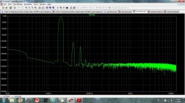
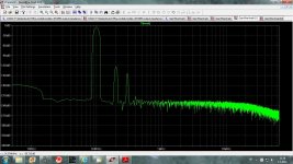
Discussion, in an other thread, about the need to have SUPER HIGH bandwidth was the reason to do some FFT simulation at 20kHz, 100kHz and 1MHz.
Here are the simulations only, I hope that the real result will be not far from it.
dado
Here are the simulations only, I hope that the real result will be not far from it.
dado
Attachments

Sergio.. would it be possible to make something like the circuit in post #180 with balanced in..??
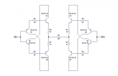
Will that also be possible to sum into a single ended output..??.. like for use with balnces out DAC's or for a balanced in pre-amp.
The outputs will be the sum ( of the differences) of the two inputs, If you need single end ouput just use one of the outputs and let the other unconnected .
Where do you want to use a circuit like this ? In a passive I/V converter ?
I Also have interess in this type of circuit , but is not a priority , for now I am just observing what dadod is achieving.
Where do you want to use a circuit like this ? In a passive I/V converter ?
I Also have interess in this type of circuit , but is not a priority , for now I am just observing what dadod is achieving.
Last edited:
For the PCM 179x the output is differential. there the balanced in can be an advantage, also if one would like to make a flexible line stag where you would want both balanced and single ended inputs this circuit could be of interest. As earlier mentioned I see this concept strong, as i gets better spec.s as you reduce the gain. With a suitable output buffer it will be possible to make a Pre-amp/DAC with a non degrading volume control.
Mirror_bjt.asc I have post the models in here already.
Hi Sergio
your circuit is oscillating
run sim at 1ns timestep
Pawel , erase C3 and C4.
That circuit was never built. is only a topology idea, not a finished project. So, use at your one risk 🙂
That circuit was never built. is only a topology idea, not a finished project. So, use at your one risk 🙂
As earlier mentioned I see this concept strong, as i gets better spec.s as you reduce the gain. With a suitable output buffer it will be possible to make a Pre-amp/DAC with a non degrading volume control.
Michael I like the concept also, but unfortunely my spare time is limited , The job and my wife, takes me a lot of time, and I need both of them.
I envy your Job 🙂, I would also love to only work in AUDIO. Your loudspeakers are impressive.
Pawel , erase C3 and C4.
you were right,
how would you controll the offset and gain?
- Status
- Not open for further replies.
- Home
- Source & Line
- Analog Line Level
- Current conveyor as a voltage amplifier