Hi,
You could always try to ping Jonathan Carr...
In the mean time the loading effects on a MC cartridge are well understood I think?
PRAT I'd leave that to the TT, not the cartridge...
Cheers,😉
I am sorry that we got no feedback from MC cartridge designers.
You could always try to ping Jonathan Carr...
In the mean time the loading effects on a MC cartridge are well understood I think?
PRAT I'd leave that to the TT, not the cartridge...
Cheers,😉
PRAT I'd leave that to the TT, not the cartridge...
I'd leave that to the musicians, not the hifi gear.😉
The trial-and-error of cartridge loading is well-known; I'm not as certain as you that it's well-understood in the sense of being able to look at some cartridge specs and predict the optimal load. There's too much else going on at the transduction end, and the loading can either help or hurt that.
Just curious, who has studied the effects (or non-effects, if that's the case) of loading on trackability?
Hi,
It's easily visible on the oscope as far as frequency response is concerned...
Trackability and MCs don't go hand in hand all that well, the lower the loading_upto a point_ the better the tracking generally speaking.
With my own J.A.s and a tube based I/V I go from a lowish 47R to a high 51K: the low loading has tighter bass and greater dynamic range at the expense of rather shut in highs.
I usually go for what suits my taste/system/cartridge/arm best, not necessarilly for what tracks best...
I don't listen to the 1812 Overture torture tracks for the fun of it, you know.😉
Cheers,😉
P.S. I'm not surprised at all to see john C. frown at the recommended 845 Ohm loading for the MC Finnish, 100 R suits it better IMHO...Just don't tell Jan I told you this.
Would you believe this is done by hand?
Just curious, who has studied the effects (or non-effects, if that's the case) of loading on trackability?
It's easily visible on the oscope as far as frequency response is concerned...
Trackability and MCs don't go hand in hand all that well, the lower the loading_upto a point_ the better the tracking generally speaking.
With my own J.A.s and a tube based I/V I go from a lowish 47R to a high 51K: the low loading has tighter bass and greater dynamic range at the expense of rather shut in highs.
I usually go for what suits my taste/system/cartridge/arm best, not necessarilly for what tracks best...
I don't listen to the 1812 Overture torture tracks for the fun of it, you know.😉
Cheers,😉
P.S. I'm not surprised at all to see john C. frown at the recommended 845 Ohm loading for the MC Finnish, 100 R suits it better IMHO...Just don't tell Jan I told you this.
Would you believe this is done by hand?
Attachments
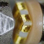
A steadier hand than mine!
In these days of 3-D circuits and microfab, it strikes me that you could do this a lot better without discrete wire.
In these days of 3-D circuits and microfab, it strikes me that you could do this a lot better without discrete wire.
Hi,
Quite possibly.
Jan A. however is an absolute control freak...One I greatly respect.
A friend of mine once offered to have his "Eco" range made by Benz Micro so Jan could concentrate on the more "High-End" stuff but he flatly refused even after we tactfully explained the economics of the deal.
BTW, just out of curiosity: is there a reasonable way to do current amplification with tubes at these levels or is my I/V conversion a better way to avoid too high noise penalties?
Cheers,😉
In these days of 3-D circuits and microfab, it strikes me that you could do this a lot better without discrete wire.
Quite possibly.
Jan A. however is an absolute control freak...One I greatly respect.
A friend of mine once offered to have his "Eco" range made by Benz Micro so Jan could concentrate on the more "High-End" stuff but he flatly refused even after we tactfully explained the economics of the deal.
BTW, just out of curiosity: is there a reasonable way to do current amplification with tubes at these levels or is my I/V conversion a better way to avoid too high noise penalties?
Cheers,😉
fdegrove said:BTW, just out of curiosity: is there a reasonable way to do current amplification with tubes at these levels or is my I/V conversion a better way to avoid too high noise penalties?
Cheers,😉
Smugness aside, what are you talking about ?
I know next to nothing about tubes, but I do know a valve
current gain stage without voltage gain would be a disaster.
I/V conversion is another way of saying output voltage loaded by
the internal resistance, its still really V/V conversion, after all the
cartridge is a voltage source, not a current source.
And I/V conversion goes wrong when the combination of internal
resistance and inductance does not allow a flat current response
equivalent to the higher impedance voltage response, unless this
is designed into the cartridge response, suiting shorted loading.
🙂 sreten.
Usually this is not a problem. For some reason, intrinsic cartridge resistance seems to dominate the frequency response over the audio bandwidth. We don't actually know why MC cartridge loading actually makes a difference, but it does. Only cartridge designers could help us here.
Cartridge load;
may it be that MC pickup has its stylus directly electrically and mechanically connected to the cartridge input impedance, the MM pickup stulys is not directly electro-mechanically connected but more a magneto-mechanically connected which loads it's stylus diffrent electrically.
Just some thoughts...
Cheers 🙂
I'm looking at a current input, current feedback transimpedance preamp design for a moving magnet cartridge, hoping the low input impedance will get around the effects of stray capacitance that bedevil moving magnet designs with high intrinsic inductance. The application is a radio station/studio environment where Stanton 680s are the norm - can't change that. The cartridge has about 950mH inductance and about 1.2k intrinsic resistance. This really makes it difficult to terminate properly and get optimum noise and/or frequency response. The circuit I'm contemplating for initial cartridge interface is a variation of a 3-transistor current input, current feedback transimpedance preamp used by Hamamatsu as a photomultiplier tube preamplifier. Jan Didden used a similar circuit quite a while back as an I-V converter for a 1541 DAC. The input is common base, with a common emitter gain stage, and emitter follower output. I would add a few more pieces for bias stability, and maybe a servo to hold the current summing junction at 0V. I'm interested to see what happns when you treat a fairly crappy cartidge like the Stanton 680 as a current source operating into a low impedance summing node.
I'm interested to see what happns when you treat a fairly crappy cartidge like the Stanton 680 as a current source operating into a low impedance summing node.
My guess: nothing good. It is designed to produce relatively linear output in 47k and will certainly not do the same into a common base input. Would the complete absence of high frequencies not be a hindrance?
Hi,
FWIW, the Stanton 68x series aren't even MM cartridges but rather of the moving iron variety.
Not that it would matter for what you're trying to do but still.
Dunno what exactly it was JD did but I know a few reasons why one would go down that road for I/V conversion in a DAC (not all of them) iso using say, a resistor, resistively loaded xformer or the ubiquitous opamps.
Catridges aren't DACs and vice versa....so I second Analog_sa 100% here.
Cheers, 😉
I'm interested to see what happns when you treat a fairly crappy cartidge like the Stanton 680 as a current source operating into a low impedance summing node.
FWIW, the Stanton 68x series aren't even MM cartridges but rather of the moving iron variety.
Not that it would matter for what you're trying to do but still.
Jan Didden used a similar circuit quite a while back as an I-V converter for a 1541 DAC.
Dunno what exactly it was JD did but I know a few reasons why one would go down that road for I/V conversion in a DAC (not all of them) iso using say, a resistor, resistively loaded xformer or the ubiquitous opamps.
Catridges aren't DACs and vice versa....so I second Analog_sa 100% here.
Cheers, 😉
john curl said:...
This overdamped the MC cartridges. I proved this by rewiring the design to be switchable to either 100 ohms input or grounded base (very low Z) and listened to the difference. 100 ohms input won the contest.
Could you please elaborate as to the sonic difference between the two approaches? There tends to be some differences of opinion about which sound more closely approximates the source. And, I'm curious about whether the sonic improvement was, as you say, due to reducing the cartridge damping, or due to other things, such as increasing the damping of the Q of the inductor, etc..
Hi,scott wurcer said:Brian - If you want a quick try on this, take the lowest _voltage_ noise CFA you can find, use the cartridge resistance as gain resistor and an appropriate resistor as feedback resistance to get the gain. So if you have a cartridge that measures 5 Ohms say use a 500 Ohm feedback resistor. I don't think any offsets get in the way current or voltage (a few microAmps one way or the other flow in the coil). OTOH you might want to select for lowish Vos or tweek it (pot on the rails with a big divider to the +input, for instance).
in my current project (a deviation from rjm's phonoclone), I use the AD811 in the way Scott described here some time ago. I've tried some other chips here, (both cfa and 'normal'), but that one works best. That with -probably Ri-wise- suboptimal DL103.
But, I have a strange issue: without tweaking the offset, I have an input offset of around 0.2 - 0.4 mV. It works with the denon cartridge, but i fear it would fry a cart with say Ri=1 Ohm.
However, if I tweak the offset to zero as described by Scott, the sound gets dull as if the tweeter is missing. Can that be? Or is this something else going wrong?
Rüdiger
current amplifying phono stage for MM input
the mentioned topology by the URL
RJM Audio - The Phonoclone Phono Preamplifier
is appropriate for MC cartridges with low RDC VALUES like Audio Technica OC9, Ortofon Rohman or several devices from Lyra.
By the use of usual MM cartridges Rin rises up to 47 K and consequently Rf rises up to 470K until 3000K. Thus the signal to noise ratio is worse.
Exist an approach to avoid this unwanted effect by maintaining this I/U topology?
Dynavector has built one. Someone mentioned a related patent in the beginning of this thread. I own one DV PE-1, but I have no circuit diagram of it 😡 It contains opamps and transformers, and allegedly has zero input impedance. You can find much information about the "phono enhancing" and the similar "P-75 phonostage" on the web.Just curios to discover if anybody has built any phono from what it has been discussed here?
maybe Musical Fidelitie's A1 uses such an approach - go tothe mentioned topology by the URL
RJM Audio - The Phonoclone Phono Preamplifier
is appropriate for MC cartridges with low RDC VALUES like Audio Technica OC9, Ortofon Rohman or several devices from Lyra.
By the use of usual MM cartridges Rin rises up to 47 K and consequently Rf rises up to 470K until 3000K. Thus the signal to noise ratio is worse.
Exist an approach to avoid this unwanted effect by maintaining this I/U topology?
Musical Fidelity A1 - Technical
Nope the A1 RIAA is voltage input, and with 56Kohms and poor noise figure not not really suited for MC's. And they could have chosen a low offset opamp, so at least they could do without the output cap..
whither overdamping
I went to see where this term had been discussed, besides recent exchanges on the Blowtorch thread, and wound up here. At least it was fairly easy to read through, based on the relatively modest thread length.
Since reading various articles including Bob Cordell's phono preamp article in Didden's bookzine, I've been pondering the pros and cons of realizing some part of the RIAA equalization by using the inductance and resistance of the cartridge. Among the cons is the need to know the precise impedance of the cartridge, which undoubtedly varies from sample to sample; in addition there will be a temperature coefficient associated with various things like the magnetic materials and the wire, for both MM and MC. So this needs to be accurately determined and the impact assessed.
Another factor to be considered is the variation in inductance as a function of stylus motion. I measured this for a very large displacement on an old M91E and found it measurable but quite small.
Another con is the attentuation of the signal, and in the Cordell article he stopped short of realizing the 75us pole entirely via resistive loading, citing signal-to-noise concerns.
What benefits may proceed from overdamping remain to be seen. Cordell has stated that he saw very little effects of reciprocity, that is, the damping of the electrical did not apparently translate into a significant change in the mechanical behavior. Of course there has to be some effect, but if sufficiently small it's probably tolerable (or possibly even desirable in specific cases).
So, despite these potential or actual disadvantages, what can one do to do the best job possible? And how far can the approach be taken?
It might be supposed that the noise contribution of the smaller-than-normal termination resistor is inevitable. But we know that using synthetic "cooled" terminations that can be minimized. Some less-than-optimal examples have been presented in recent books, which use auxiliary amplifiers. There are other ways that work better.
But what about the cartridge that, it would seem, can at most damp itself using its own internal resistance operating into a virtual ground, the "I-V converter" approach discussed and referenced in this thread? What if the L/R time constant is too small to do much, as might be the case with low inductance MC cartridges?
I propose making the input impedance less than zero, over a safely restricted and controlled bandwidth. Provided the net resistance is positive the value of it can be adjusted to provide any desired L/R time constant. In addition, in many cases, you will get voltage gain. It is even possible, it would seem, to realize the 3180us tau, with the circuitry following introducing compensation to yield the overall desired RIAA.
Anyway, I'm working on this, but I thought it worthwhile to throw these ideas around, particularly if someone should happen to know of any similar speculations or even actual designs. By publishing here I also am attempting to prevent independent patenting that might prevent the use of some of the approaches, so they remain available, for what it's worth.
Brad
Brad, you can work out how much damping you can manage using the usual Electrodynamic relations.
Voltage = Blv v: stylus velocity
Force = Bli i: current in coil.
These are exact for MC cartridges. Moving Magnet & Moving Iron are more complicated but well within a factor of 2 of this.
The mechanical resistance you can introduce by shorting the cartridge is (Bl)^2/Rdc
These are the same eqns as for dynamic speakers.
With -ve resistance, you can 'reduce' Rdc and get more damping.
But in practical cartridges, there is ALREADY TOO MUCH DAMPING.
Look up the Shure papers on Trackability & design of extended BW cartridges for chapter & verse.
What would be useful is to introduce -ve mass at the stylus tip All it needs is some Unobtainium 🙂
Last edited:
- Status
- Not open for further replies.
- Home
- Source & Line
- Analogue Source
- current amplifying phono stage