Finally got around to hooking up both Cubie2 amps, (4 channels), bi-amping my Maggie MG1.6...Sweet!!! I was concerned I would end up with some hum hooking two amps to a single source...dead silent. Paying attention to the avoidance of ground loops pays big dividends! Still won't rock the foundation, but it effortlessly achieves my desired listening level. Sounds right, real, spacious, quick, transparent... not doughy or ponderous, not opaque, not veiled. F5 driving two 18" subwoofers in cabinets the size of clothes washers/dryers. (10 cu ft. each). Oh for 200 watts of amplification that sounds like this!
Thanks, juma!!!-mars
Thanks, juma!!!-mars
Hi Juma,
I have parts to build this amp except jfet. It hard to find locally, can you redesign Cubie2 input BJT? Thank you in advance.
Regards,
Boyet
I have parts to build this amp except jfet. It hard to find locally, can you redesign Cubie2 input BJT? Thank you in advance.
Regards,
Boyet
... redesign Cubie2 input BJT? ...
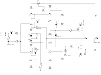
Here it is. All LEDs are simple 3mm red. The bias will be about 0.7A through the output stage. If you want it higher (about 1A) use 3 mm green LEDs for D3, D4. If you want less bias use 1n4148 instead of D3 or D4 (or both). Take care about polarity.
Experiment, listen and measure.
If you go for lower bias add 470u - 1000u power rail bypass caps close to MOSFETs' drains.
Use good caps for C2, C4, C5 (ELNA Silmic or similar). 6.3V is a minimal voltage rating, you can also use 10 or 16V devices.
P1 sets the DC offset at the output.

Attachments
Last edited:
What about adding a low value resistor between D3 & D4, to allow fine trimming of the output pair bias voltage?
Would an added resistor ruin the performance of Cubie2?
Or maybe going for lower voltage diodes and a higher resistance for the bias adjuster?
Would an added resistor ruin the performance of Cubie2?
Or maybe going for lower voltage diodes and a higher resistance for the bias adjuster?
No need for fine trimming.
Less than 250 mA won't sound really good and more than 1A won't bring any benefit. Anywhere between 0.6 and 0.8A will do just fine.
Less than 250 mA won't sound really good and more than 1A won't bring any benefit. Anywhere between 0.6 and 0.8A will do just fine.
Here it is. All LEDs are simple 3mm red. The bias will be about 0.7A through the output stage. If you want it higher (about 1A) use 3 mm green LEDs for D3, D4. If you want less bias use 1n4148 instead of D3 or D4 (or both). Take care about polarity.
Experiment, listen and measure.
If you go for lower bias add 470u - 1000u power rail bypass caps close to MOSFETs' drains.
Use good caps for C2, C4, C5 (ELNA Silmic or similar). 6.3V is a minimal voltage rating, you can also use 10 or 16V devices.
P1 sets the DC offset at the output.
Thank you very much Juma 🙂 🙂
So, after reading the whole thread, I was convinced to build the Cubie2 amp. Reading it, a bunch of questions came up, which I'm posing here:
1. Do the input JFETS need to be matched between p- and n- type and/or between channels?
2. Do the bipolar transistors need to be matched? If yes, should this matching be between PNP and NPN type, between channels, or what? Also, this matching is regarding the hFE of the transistors?
3. In the capacitor multiplier circuit of the PSU, what is the wattage of R1/R2 and R5/R6 resistors?
4. What is a suitable VA rating for the transformer? Is a 200VA TX adequate?
5. What is a satisfactory heat dissipation rating for each heatsink, assuming that each heatsink dissipates for one channel and one PS rail MOSFET? Juma, what are the dimensions of the heatsinks that you used in the photos for your Cubie2?
That's all for now.
Vagelis
P.S. Juma, in one of the pictures in your first post, I noticed a packet of KARELIA cigarettes. Is that your brand?
Newbie here, Is any pcb figure available matching this schematic?Here it is. All LEDs are simple 3mm red. The bias will be about 0.7A through the output stage. If you want it higher (about 1A) use 3 mm green LEDs for D3, D4. If you want less bias use 1n4148 instead of D3 or D4 (or both). Take care about polarity.
Experiment, listen and measure.
If you go for lower bias add 470u - 1000u power rail bypass caps close to MOSFETs' drains.
Use good caps for C2, C4, C5 (ELNA Silmic or similar). 6.3V is a minimal voltage rating, you can also use 10 or 16V devices.
P1 sets the DC offset at the output.
Unfortunately i haven't and can't find any 2sk170 not j74 fet to be able go for the original version.🙁
Last edited:
Giasou Vageli !..a bunch of questions ...
1. No / no. But if you have matched pairs it could only make it better - staying in same range (GR or BL) is enough
2. hfe and Vbe inside current mirrors (and inside one channel) and Q6 to Q7 (one to one and channel to channel) would be nice but it's not mandatory
3. 1/4W all
4. Yes
5. about 30W per channel, use any heatsink that can take that without a temp. raise of more than 20 degrees above ambient. Those that I used are too small for Greek summer.
P.S. Auta einai ta agapimeni mou 😉
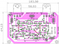
No, I tested the point-to-point prototype only, but it's easy to adapt the original layout - it's few parts only...Newbie here, Is any pcb figure available matching this schematic?...
Don't worry about JFETs, BJT input won't disappoint you, just make sure to use some buffer or preamp at the input - IME putting a pot directly to BJT input is not the best solution.
Thanks Juma!No, I tested the point-to-point prototype only, but it's easy to adapt the original layout - it's few parts only...
Don't worry about JFETs, BJT input won't disappoint you, just make sure to use some buffer or preamp at the input - IME putting a pot directly to BJT input is not the best solution.
I will try to find a pcb designer😉
Prasi,Alex are you here?😀
5. about 30W per channel, use any heatsink that can take that without a temp. raise of more than 20 degrees above ambient. Those that I used are too small for Greek summer.
Geia sou Juma!
Thank you for your response.
Thus, I think that a heatsink with a resistance of ca. 0.5 deg.C/W would be more than adequate.
Best regards,
Vagelis
Exicon sells laterals that are a replacement for the k1058 & j162. I used pairs of the ECX10N20 and ECX10P20 for my F7 clone and they appear to work great. I am not sure if this has been mentioned in this topic. I may build this amplifier myself.
Exicon Lateral MOSFETS - Cross-reference Charts
Exicon Lateral MOSFETS - Cross-reference Charts
Newbie here, Is any pcb figure available matching this schematic?
Unfortunately i haven't and can't find any 2sk170 not j74 fet to be able go for the original version.🙁
If you search in ebay, you may find them. Problem is that it's not guaranteed that they are genuine Toshiba FETs
I do have some at home (over 100 pairs), they are 100% originals purchased from Mouser about 9 years a go.
I have both type few GR and BL I already match them for own use.
I do not plan to sell any of them may be trade for 2PC Black Gate 10uF Non polar caps. The red one only, can be 25 or 35V or so. Other than I need some Sanken power device to my NAIM clone I want to compare against the ON Semi high power devices. Again these not so easy the market flooded with fake semiconductors. I would rather order those from Mouser or Digi-Key. Time to time you can find them on the forum. I can feel your pain, I had 16 PC those Black Gate caps in my Aleph 1.7 I sold them, now I need two piece.
I will never buy these fake.If you search in ebay, you may find them. Problem is that it's not guaranteed that they are genuine Toshiba FETs
Buy genuine Exicon .
I will never buy these fake.
Buy genuine Exicon .
You can be sure that any of the desirable transistors that are obsolete on Ebay from China are fakes. Some reputable sellers do sell genuine parts on Ebay but it is always a gamble unless someone on this forum recommends them. Buyer beware. Our store has the j-fets and Profusion sells the Exicon's. One will spend more on fakes with disappointments than taking the sure route. Been there done that.
Profusion Shopping Cart
Thanks Juma!
I will try to find a pcb designer😉
Prasi,Alex are you here?😀
Yassou, my Greek friend!.
is this what you are looking for?
regards
Prasi
Attachments
Last edited:
- Home
- Amplifiers
- Pass Labs
- Cubie2