Build one by yourself. You can even get 7.1 with BTM581 module (but not with BTM383) with proper DAC and some programming.I'm open to suggestions with chip amps providing they are easily customisable
@o11111 probably a bit beyond my skillset, i paid someone on fivver to design me a PCB which had a TP4056 BMS, spst switch allowance 3 boost converters to 6.5v and 2x 5v and some points for LEDs for charging etc all on that 30x30mm board, then got them made up on JLPCB. I cant find any of the gear for the amp unfortunately otherwise i'd try commision one with the above plus the amp/chip and pinout for easy programming
@mahaju i have some of the newer version just had issues getting it to work. I got to rename the module though, but it wouldnt let me use some japanese characters that i was trying for (dont ask) where i could using the older tech.
i'm using qcc3003 and a QCC3034, but its a different process syncing it to the pc. I also think there is an issue with the QCC3034 range and the onboard voltage booster that causes brownouts, have you encountered that?
i'm using qcc3003 and a QCC3034, but its a different process syncing it to the pc. I also think there is an issue with the QCC3034 range and the onboard voltage booster that causes brownouts, have you encountered that?
You don't need to design full PCB with amp chip etc, actually. Just a simple breakout board is everything you need (and I think I've shared kicad project somewhere in this topic). You can use BTM581 module and just any off-the-shelf amp board (i.e. TPA311x) with it directly without external DAC. QCC5181 is plenty powerful for digital crossover (which you could use in combination with TWS capabilities to make stereo pair of speakers), so it will greatly simplify analog circuitry and make it much more flexible.I cant find any of the gear for the amp
I have DAC with SPDIF input. I would like to connect my phone via bluetooth/ldac to it.
I have found out that it is possible to buy this modules on aliexpress:
BTM525 QCC5125 LDAC APTX-HD APTX-LL I2S IIS SPDIF bluetooth
Is it sufficient that I connect +3.3V power supply and spdif pin directly ?

I have found out that it is possible to buy this modules on aliexpress:
BTM525 QCC5125 LDAC APTX-HD APTX-LL I2S IIS SPDIF bluetooth
Is it sufficient that I connect +3.3V power supply and spdif pin directly ?
The image is for CSR8675, but you're referring to QCC5125. Both are not recommended and will require at least connecting the antenna. Schematic example is here.Is it sufficient that I connect +3.3V power supply and spdif pin directly ?
Thanx,Schematic example is here.
finally I have decided to buy this one:
/CSR8675 Bluetooth V5.0 Low Power Bluetooth Audio Module Receiver Board APTX-HD Lossless Compression I2S Fiber SPDIF/
It has antenna-like thing build in, so requirement of bt antenna should not be an issue anymore
Something that worries me is that LDAC is not present in aliexpress item description. Do I need to turn it on during programming ?
Very last thing : I'm curious if quality of sound from built-in dac after connecting via opamp to amplifier will be much worse than CSR8675 <-spdif-> DAC <-RCA-> configuration.
Simple answer: you will not get LDAC.Something that worries me is that LDAC is not present in aliexpress item description. Do I need to turn it on during programming ?
More complicated one: it's possible, but requires programming skill. You will spend years working on that (ask me how I know, tho I've worked with QCC51xx). There is absolutely no reason to work with CSR867x, it's already obsolete.
If you don't want to make you own PCB with antenna, you'll have to go for off-the-shelf boards, like this or this.
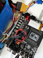
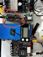
Hi, i'm newbie here. I'm building a stereo system like a boombox and implementing smart features using ESP32 S3 (without LE audio unfortunatelly) so i'm using QCC5171 for bloetooth audio and a DAC ES9038Q2M . I've purchase an empty chip QCC5171 and this development board. I think that explanation is usefull for me. Have you sample code for QCC5171?Are you sure Attiny85 has enough performance? QCC5171 definitely has, also it has FFT library included, so it's not that hard to implement the DSP code itself. It will have 2 inputs (stereo audio) and 3 outputs (stereo audio + spectrum data). As always, the interaction is the hardest part. You'll have to modify some code for application core, but I thing that using SinkMap (firmware will take care about audio and you will only need to send this data to LEDs). Maybe it's a wise idea to still use Attiny, but just for periphery: OLED and WS2812B. This way QCC5171/44 will do all the heavy lifting and Attiny will just receive data via UART (see this or this).
It depends. You will have to right code for QCC either way, but if you'd go with BLE approach, you won't have to write a lot of code for your smartphone. If you'll implement BLE Nordic UART Service (NUS), you would be able to use already existing ecosystem of apps which support it.
GAIA, on the other hand, is different for QCC3031 and QCC5144/71, and QCC3031 GAIA app is available in source code form only for Android. It's also quite old at ~4 years, so it would be hard to implement. BLE NUS will be very similar between QCC5144/71 and QCC3031, so in case you will switch to them later, it would be pretty easy to port the code.
80-CF422-1.pdf
Programmable DSP (so LDAC or LC3plus HR possible), better software architecture. QCC5171 is dual-core @240MHz, while QCC5144 is only 120Mhz. Given (almost) the same price, QCC5171 is better (at 14$ it's actually little bit cheaper than QCC5144 at 15$, no ideas why tho).
So I would recommend using BLE, DSP for processing the audio and separate MCU for controlling the periphery via UART. You can certainly get rid of the separate MCU, but it will be a bit harder to code. Or you can get rid of the DSP code and use something like Raspberry Pi Pico (5$) for light effects (it also has ADC, so you can connect it to line out of the QCC)
I can help you with such a project, send me a PM with your GitHub account name and I will add you to private repo with QCC5171 (or QCC5144. They're almost the same) firmware (stock). You'll have to write most of the code by yourself, but I will help you in case of problems.
Last edited:
You can ask seller of dev board to provide it or download it here.Have you sample code for QCC5171?
The seller sent me all environment dev, but the projects in src code is for earbud or handset, in my case i want something more simple, and integrate it with the ESP32 via i2c if possible. Do you know if have something like this?You can ask seller of dev board to provide it or download it here.
There's loopback app, it's as simple as it gets. Or what do you want? You add ENABLE_SIMPLE_SPEAKER define to disable most of unnecessary headset stuff, but make sure that you have recent version (r00496.1 or later should have it) which contain this #ifdef.something more simple
Sure, I've updated my files and now i can see ENABLE_SIMPLE_SPEAKER. The docs tells that it's for car (audio system) or simple stereo system 🙂. I think it's works for me. Thanks so much(r00496.1 or later should have it) which contain this #ifdef.
@o11111 I've compiled the workspaces (LEA and without it) with the def ENABLE_SIMPLE_SPEAKER but the bluetooth pairing only get paired with my macbook pro m1, with my iphone 13 this aways fails without much log about it. I've tried it without the speaker flag too but no success. Do you know anything about it?
Only exception displayed in log when i try pair to the iphone 13 is:
2567.175 apps1: 68: LOG_INFO (CsrBtCmLto): CsrBtCmDmArrivalHandler cat:0x0 MESSAGE:dm_prim_tag:0x1e (ENUM_DM_HCI_SLAVE_PAGE_RESPONSE_TIMEOUT_IND)
2567.175 apps1: 69: LOG_WARN (CsrBtCmLto): Exception: EventClass=0x4, PrimType=0x0, State=0x1, [bt/profile_managers/cm/code/csr_bt_cm_dm_arrival_handler.c:1165]
What's the value of XtalLoadCapacitance in subsys0_config3.htf? All dev boards I have require it to be 23, but default is 10. Change it and try once again.bluetooth pairing
You shouldn't be using QCC51xx with anything other than Android phones with recent Snapdragons (6/7/8g1 and newer, not Samsung). All apple stuff is simply not good for audio on its own (tho it could be still usable with USB transmitter dongles)iphone 13
Works like a charm. Very thanksWhat's the value of XtalLoadCapacitance in subsys0_config3.htf? All dev boards I have require it to be 23, but default is 10. Change it and try once again.
Sure, apple always get issues with technologies out of your ecosystem 🙁. But unfortunately i'll need to deal with it cuz my project is a "stereo boombox".You shouldn't be using QCC51xx with anything other than Android phones with recent Snapdragons (6/7/8g1 and newer, not Samsung). All apple stuff is simply not good for audio on its own (tho it could be still usable with USB transmitter dongles)
Anyone have integration with external dac? I'm trying set pios explaned in the board schamatic, but it isn't works, if i set the def INCLUDE_SSM2518_I2S_AMP gets panic.
subsys3_config2.htf
# Select PIOs for I2S interface 1: SCK, WS, MCLK, SD_OUT, SD_IN.
Pcm1PioConfig = [ 10 11 0F 12 13 ]
MCLK is not needed because my ES9038Q2M module has an independent clock of 100M
subsys3_config2.htf
# Select PIOs for I2S interface 1: SCK, WS, MCLK, SD_OUT, SD_IN.
Pcm1PioConfig = [ 10 11 0F 12 13 ]
MCLK is not needed because my ES9038Q2M module has an independent clock of 100M
Attachments
@LOGICSB,
use PcmPioConfig (without 1, so it's for 0th I2S instance) and add ENABLE_I2S_OUTPUT define.
use PcmPioConfig (without 1, so it's for 0th I2S instance) and add ENABLE_I2S_OUTPUT define.
Is obviously not going to work unless you have SSM2518 as this define is mainly for I2C amp control (i.e. volume).INCLUDE_SSM2518_I2S_AMP
- Home
- Source & Line
- Digital Line Level
- CSR8675 programming guide w software and tons of CSR info

