Still waiting for the boards to arrive, hopefully this week!
Brett, I can get the boards made for you or provide Gerbers if you prefer to go direct. Either way, it's worth waiting until these first ones come back to be sure there's no errors 🙂
Brett, I can get the boards made for you or provide Gerbers if you prefer to go direct. Either way, it's worth waiting until these first ones come back to be sure there's no errors 🙂
Still waiting for the boards to arrive, hopefully this week!
Brett, I can get the boards made for you or provide Gerbers if you prefer to go direct. Either way, it's worth waiting until these first ones come back to be sure there's no errors 🙂
If you dont mind providing gerbers im considering creating some at my campus. 😛
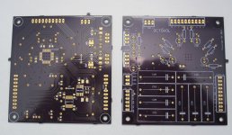
The boards arrived on Thursday, I've since had time to assemble mine 🙂
Board quality appears very good, I pushed the limit of the silkscreen at points but all the designators are legible. Nice gold finish on the pads, solderability was great all round, no thermal issues with this design either. Through hole plating seems consistent.
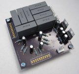
I assembled the board partly at a re-work bench but left the through hole parts to do at home. That was a mistake, I should have done all of the soldering at the re-work bench as my Antec iron is a bit too clumsy for these pads! It should work fine anyhow but I recommend using the best equipment you can. Soldering the CS3318 was no problem at all, the ground area beneath it doesn't draw heat away in any noticeable way, you won't have a problem if you have good magnification and a fine gauge solder.
I wish I had ordered 10-way Molex instead of 12-way, not sure how I managed that 😱 . I also forgot R19 but it isn't critical. I'll see about writing some basic software to drive this, just using a pot and the master channel volume register at first I think. Then the design can be validated 🙂
Board quality appears very good, I pushed the limit of the silkscreen at points but all the designators are legible. Nice gold finish on the pads, solderability was great all round, no thermal issues with this design either. Through hole plating seems consistent.
I assembled the board partly at a re-work bench but left the through hole parts to do at home. That was a mistake, I should have done all of the soldering at the re-work bench as my Antec iron is a bit too clumsy for these pads! It should work fine anyhow but I recommend using the best equipment you can. Soldering the CS3318 was no problem at all, the ground area beneath it doesn't draw heat away in any noticeable way, you won't have a problem if you have good magnification and a fine gauge solder.
I wish I had ordered 10-way Molex instead of 12-way, not sure how I managed that 😱 . I also forgot R19 but it isn't critical. I'll see about writing some basic software to drive this, just using a pot and the master channel volume register at first I think. Then the design can be validated 🙂
Attachments
Thanks 🙂
Not getting anything through to the output although it seems healthy otherwise. Rails are present and correct, no output offset or noise on any channel. I don't have a digital scope but the data, clock and CS can be seen passing through the isolator up to the chip. Reset is coming high at the chip too.
Anything obvious I've missed in this code? It's an adaptation of a simple PGA2310 driver using PIC 12F675.
I think I've set everything up right but still not passing a signal 😕
Not getting anything through to the output although it seems healthy otherwise. Rails are present and correct, no output offset or noise on any channel. I don't have a digital scope but the data, clock and CS can be seen passing through the isolator up to the chip. Reset is coming high at the chip too.
Anything obvious I've missed in this code? It's an adaptation of a simple PGA2310 driver using PIC 12F675.
Code:
// CONFIG
#pragma config FOSC = INTRCIO   // Oscillator Selection bits (INTOSC oscillator: I/O function on GP4/OSC2/CLKOUT pin, I/O function on GP5/OSC1/CLKIN)
#pragma config WDTE = OFF       // Watchdog Timer Enable bit (WDT disabled)
#pragma config PWRTE = OFF      // Power-Up Timer Enable bit (PWRT disabled)
#pragma config MCLRE = ON       // GP3/MCLR pin function select (GP3/MCLR pin function is MCLR)
#pragma config BOREN = OFF      // Brown-out Detect Enable bit (BOD disabled)
#pragma config CP = OFF         // Code Protection bit (Program Memory code protection is disabled)
#pragma config CPD = OFF        // Data Code Protection bit (Data memory code protection is disabled)

#include <htc.h>
#define _XTAL_FREQ 4000000

#define SPCS GP2
#define SPCLK GP5
#define SPDAT GP4
#define RESET GP1


int getVoltage (void)

	{
		ADCON0bits.GO=1;
		while (ADCON0bits.GO==1);
		return(ADRESH<<8|ADRESL);
	}


void SPI_send (unsigned char data)

	{
	char counter = 0;

	for(counter = 8; counter; counter--)
	{
		if (data & 0b10000000)
			SPDAT = 1;
		else
			SPDAT = 0;
		data = data <<1;

		SPCLK = 1;
		__delay_us(20);
		SPCLK = 0;
		__delay_us(20);
	}

	}

void main (void)

{
	int ADold = 0;
	int ADnew = 0;
	char SPIdata = 0;

	ADCON0 = 0b10000001;
	ANSEL  = 0b01100001;

        CMCON = 0b00000111;

	TRISIO = 0b00001001;

        RESET = 1;
        __delay_ms(20);


        /* Device Configuration */
        SPCS = 0;
        SPI_send (0x40);
        SPI_send (0xb);
        SPI_send (0b00010000);
        SPCS = 1;

        __delay_us(20);

        /* Device Configuration 2 */
        SPCS = 0;
        SPI_send (0x40);
        SPI_send (0xc);
        SPI_send (0b00001101);
        SPCS = 1;

        __delay_us(20);

        /* Master Power */
        SPCS = 0;
        SPI_send (0x40);
        SPI_send (0xe);
        SPI_send (0b00000000);
        SPCS = 1;

        __delay_us(20);

	while(1)
	{

	ADnew = getVoltage();

	if (((ADnew - 2) > ADold) | ((ADnew + 2) < ADold))
	{
	   	ADold = ADnew;
		SPIdata = ADold>>2;
		SPCS = 0;
                SPI_send (0x40);
		SPI_send (0x11);
		SPI_send(SPIdata);
		SPCS = 1;
		__delay_us(20);
	}

	}
}
I think I've set everything up right but still not passing a signal 😕
Nice updates. Unfortunately i cant help you with the protocol since i have never worked with the chip. Lets see if linuxworks reacts on this 🙂
Sorry I am not much help either, I would have to dig deep into the DS to make any sense of it. If you do not know if it is HW or SW issue, then I suggest to make sure the SPI is working properly first. Usually reading a register of known value is a good start. Hooking something else up to the SPI bus to debug the HW as well.
Make sure what you are writing the data correctly as well. In my HW setup I can run diags and display on both an lcd and a terminal, so it helps a lot to figuring out what going on with out resorting to a debug tool or scopes etc.
good luck
rick
Make sure what you are writing the data correctly as well. In my HW setup I can run diags and display on both an lcd and a terminal, so it helps a lot to figuring out what going on with out resorting to a debug tool or scopes etc.
good luck
rick
I see I missed a couple of things, the chip address is 0x80 as there is a Read/Write bit on the end which shall be 0, very important, and also the errata bits weren't set:
http://www.digikey.co.uk/Web%20Export/Supplier%20Content/Cirrus_598/PDF/Cirrus_PCN_CS3308-18_B0_C0.pdf?redirected=1
Didn't think it was still relevant but perhaps it is. Anyhow, disappointingly still no output 🙁
EDIT: In terms of the SPI, I only know it works from successful use with the PGA2310, though I am writing faster now, might try increasing delay a bit.
http://www.digikey.co.uk/Web%20Export/Supplier%20Content/Cirrus_598/PDF/Cirrus_PCN_CS3308-18_B0_C0.pdf?redirected=1
Didn't think it was still relevant but perhaps it is. Anyhow, disappointingly still no output 🙁
Code:
// CONFIG
#pragma config FOSC = INTRCIO   // Oscillator Selection bits (INTOSC oscillator: I/O function on GP4/OSC2/CLKOUT pin, I/O function on GP5/OSC1/CLKIN)
#pragma config WDTE = OFF       // Watchdog Timer Enable bit (WDT disabled)
#pragma config PWRTE = OFF      // Power-Up Timer Enable bit (PWRT disabled)
#pragma config MCLRE = ON       // GP3/MCLR pin function select (GP3/MCLR pin function is MCLR)
#pragma config BOREN = OFF      // Brown-out Detect Enable bit (BOD disabled)
#pragma config CP = OFF         // Code Protection bit (Program Memory code protection is disabled)
#pragma config CPD = OFF        // Data Code Protection bit (Data memory code protection is disabled)

#include <htc.h>
#define _XTAL_FREQ 4000000

#define SPCS GP2
#define SPCLK GP5
#define SPDAT GP4
#define RESET GP1


int getVoltage (void)

	{
		ADCON0bits.GO=1;
		while (ADCON0bits.GO==1);
		return(ADRESH<<8|ADRESL);
	}


void SPI_send (unsigned char data)

	{
	char counter = 0;

	for(counter = 8; counter; counter--)
	{
		if (data & 0b10000000)
			SPDAT = 1;
		else
			SPDAT = 0;
		data = data <<1;

		SPCLK = 1;
		__delay_us(20);
		SPCLK = 0;
		__delay_us(20);
	}

	}

void main (void)

{
	int ADold = 0;
	int ADnew = 0;
	char SPIdata = 0;

	ADCON0 = 0b10000001;
	ANSEL  = 0b01100001;

        CMCON = 0b00000111;

	TRISIO = 0b00001001;

        RESET = 1;
        __delay_ms(20);

        /* Errata */
        SPCS = 0;
        SPI_send (0x80);
        SPI_send (0x00);
        SPI_send (0x99);
        SPCS = 1;

        __delay_us(20);

        SPCS = 0;
        SPI_send (0x80);
        SPI_send (0x1d);
        SPI_send (0x86);
        SPCS = 1;

        __delay_us(20);

        SPCS = 0;
        SPI_send (0x80);
        SPI_send (0x1f);
        SPI_send (0x02);
        SPCS = 1;

        __delay_us(20);

        SPCS = 0;
        SPI_send (0x80);
        SPI_send (0x0);
        SPI_send (0x0);
        SPCS = 1;

        __delay_us(20);

        /* Device Configuration */
        SPCS = 0;
        SPI_send (0x80);
        SPI_send (0xb);
        SPI_send (0b00010000);
        SPCS = 1;

        __delay_us(20);

        /* Device Configuration 2 */
        SPCS = 0;
        SPI_send (0x80);
        SPI_send (0xc);
        SPI_send (0b00001101);
        SPCS = 1;

        __delay_us(20);

        /* Master Power */
        SPCS = 0;
        SPI_send (0x80);
        SPI_send (0xe);
        SPI_send (0b00000000);
        SPCS = 1;

        __delay_us(20);

	while(1)
	{

	ADnew = getVoltage();

	if (((ADnew - 2) > ADold) | ((ADnew + 2) < ADold))
	{
	   	ADold = ADnew;
		SPIdata = ADold>>2;
		SPCS = 0;
                SPI_send (0x80);
		SPI_send (0x11);
		SPI_send(SPIdata);
		SPCS = 1;
		__delay_us(20);
	}

	}
}
EDIT: In terms of the SPI, I only know it works from successful use with the PGA2310, though I am writing faster now, might try increasing delay a bit.
Last edited:
Good point, I just added an initial condition of RESET = 0 then a 1.3 second delay. I've had an LED on this pin from the start so now you can see a delay until the device comes out of reset. No improvement though.
Some extra details, the device is ran from +/-15V bench supply being regulated to +/-8.8V on board. The digital power also comes from the +15V supply but is pre-regulated (off board) to about 5.5V to keep the ADP3301 input <12V. This helps avoid any nasties where the digital power might go down before analogue, even though it should be safe with the watchdog on the reset. The PIC is powered from USB directly, it's a desktop PC so a totally separate (and very noisy!) supply, puts the isolator under a good worst-case scenario! I apply power to the PCB then connect the USB header onto the PIC breadboard to, hopefully, start things up.
Some extra details, the device is ran from +/-15V bench supply being regulated to +/-8.8V on board. The digital power also comes from the +15V supply but is pre-regulated (off board) to about 5.5V to keep the ADP3301 input <12V. This helps avoid any nasties where the digital power might go down before analogue, even though it should be safe with the watchdog on the reset. The PIC is powered from USB directly, it's a desktop PC so a totally separate (and very noisy!) supply, puts the isolator under a good worst-case scenario! I apply power to the PCB then connect the USB header onto the PIC breadboard to, hopefully, start things up.
Well I can at least confirm the PCB works! I'm still having software issues but this code will get the Cirrus to pass a signal on all channels. Unity gain as it is supposed to be, no obvious crosstalk or noise, I'm currently only looking on the scope though.
Those delays really do need to be 2ms, even adjusting to 1ms the system stops working. I really don't know why that is, the Cirrus and isolator are much faster than this 😕
That isn't the only issue though, I still haven't got the code to work using a pot as input. I have been using LEDs on the 3 SPI wires, trying the code in slow motion etc, it appears to send the data out correctly when you move the pot. The master register did accept a single adjustment to +10dB though, I simply programmed in that static change after 5 seconds of power up and saw the signal clearly raise up.
So, still some work to do, but no issues with the PCB it seems!
Code:
// CONFIG
#pragma config FOSC = INTRCIO   // Oscillator Selection bits (INTOSC oscillator: I/O function on GP4/OSC2/CLKOUT pin, I/O function on GP5/OSC1/CLKIN)
#pragma config WDTE = OFF       // Watchdog Timer Enable bit (WDT disabled)
#pragma config PWRTE = OFF      // Power-Up Timer Enable bit (PWRT disabled)
#pragma config MCLRE = ON       // GP3/MCLR pin function select (GP3/MCLR pin function is MCLR)
#pragma config BOREN = OFF      // Brown-out Detect Enable bit (BOD disabled)
#pragma config CP = OFF         // Code Protection bit (Program Memory code protection is disabled)
#pragma config CPD = OFF        // Data Code Protection bit (Data memory code protection is disabled)

#include <htc.h>
#define _XTAL_FREQ 4000000

#define SPCS GP2
#define SPCLK GP5
#define SPDAT GP4
#define RESET GP1


int getVoltage (void)

	{
		ADCON0bits.GO=1;
		while (ADCON0bits.GO==1);
		return(ADRESH<<8|ADRESL);
	}


void SPI_send (unsigned char data)

	{
	char counter = 0;

	for(counter = 8; counter; counter--)
	{
		if (data & 0b10000000)
			SPDAT = 1;
		else
			SPDAT = 0;
		data = data <<1;

		SPCLK = 1;
		__delay_ms(2);
		SPCLK = 0;
		__delay_ms(2);
	}

	}

void main (void)

{

	int ADold = 0;
	int ADnew = 0;
	char SPIdata = 0;

	ADCON0 = 0b10000001;
	ANSEL  = 0b01100001;

        CMCON = 0b00000111;

	TRISIO = 0b00001001;

        RESET = 0;
        SPCS = 1;
        __delay_ms(20);

        RESET = 1;
        __delay_ms(20);

        /* Errata */
        SPCS = 0;
        SPI_send (0x80);
        SPI_send (0x00);
        SPI_send (0x99);
        SPCS = 1;

        __delay_ms(2);

        SPCS = 0;
        SPI_send (0x80);
        SPI_send (0x1d);
        SPI_send (0x86);
        SPCS = 1;

        __delay_ms(2);

        SPCS = 0;
        SPI_send (0x80);
        SPI_send (0x1f);
        SPI_send (0x02);
        SPCS = 1;

        __delay_ms(2);

        SPCS = 0;
        SPI_send (0x80);
        SPI_send (0x0);
        SPI_send (0x0);
        SPCS = 1;

        __delay_ms(2);

        /* Device Configuration */
        SPCS = 0;
        SPI_send (0x80);
        SPI_send (0xb);
        SPI_send (0b00010000);
        SPCS = 1;

        __delay_ms(2);

        /* Device Configuration 2 */
        SPCS = 0;
        SPI_send (0x80);
        SPI_send (0xc);
        SPI_send (0b00001101);
        SPCS = 1;

        __delay_ms(2);

        /* Master Power */
        SPCS = 0;
        SPI_send (0x80);
        SPI_send (0xe);
        SPI_send (0b00000000);
        SPCS = 1;

        __delay_ms(2);


        while(1)
        {}
Those delays really do need to be 2ms, even adjusting to 1ms the system stops working. I really don't know why that is, the Cirrus and isolator are much faster than this 😕
That isn't the only issue though, I still haven't got the code to work using a pot as input. I have been using LEDs on the 3 SPI wires, trying the code in slow motion etc, it appears to send the data out correctly when you move the pot. The master register did accept a single adjustment to +10dB though, I simply programmed in that static change after 5 seconds of power up and saw the signal clearly raise up.
So, still some work to do, but no issues with the PCB it seems!
Can you kindly use https://gist.github.com/ when you parse code, hence its awful to look through on this site.
I do not have any issues with the code captions.
Good you are on your way.
Relax, have a beer, sounds like you got lots gong today.
Good you are on your way.
I am not sure of the device command response time. Is there a busy bit to check? I will have to dig into the DS.Those delays really do need to be 2ms
Relax, have a beer, sounds like you got lots gong today.
Thanks, yes the PCB itself seems promising 🙂
Volume changes certainly can be implemented, this code toggles between +10dB and -5dB levels successfully.
https://gist.github.com/anonymous/8896632
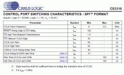
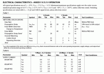
Mostly I think it is the delays which are a problem, and any possible cause which may affect data integrity like overshoot and ringing. Nowhere in the datasheets was the advice to add terminations and I never planned to run the control port much beyond 100kHz anyhow, if that, but it should be faster than it is running at now. The PIC is on breadboard too, though I've ran this same code from breadboard with 300uS or lower delays. I attach the timings from the datasheets and will see about getting the SPI clock on a loop so I can view it on my analogue scope.
Volume changes certainly can be implemented, this code toggles between +10dB and -5dB levels successfully.
https://gist.github.com/anonymous/8896632
Mostly I think it is the delays which are a problem, and any possible cause which may affect data integrity like overshoot and ringing. Nowhere in the datasheets was the advice to add terminations and I never planned to run the control port much beyond 100kHz anyhow, if that, but it should be faster than it is running at now. The PIC is on breadboard too, though I've ran this same code from breadboard with 300uS or lower delays. I attach the timings from the datasheets and will see about getting the SPI clock on a loop so I can view it on my analogue scope.
Attachments
Thanks for using gist, now we have a chance to refer to a certain line either by clicking the line number and copying the url or just referring to the number: https://gist.github.com/anonymous/8896632#file-cs3318-test-L18
Remember to choose language to get highlighting when you post a snippet. If you create a github account (for free) its easier to maintain.
Remember to choose language to get highlighting when you post a snippet. If you create a github account (for free) its easier to maintain.
Thanks, yes the PCB itself seems promising 🙂
Volume changes certainly can be implemented, this code toggles between +10dB and -5dB levels successfully.
https://gist.github.com/anonymous/8896632
Mostly I think it is the delays which are a problem, and any possible cause which may affect data integrity like overshoot and ringing. Nowhere in the datasheets was the advice to add terminations and I never planned to run the control port much beyond 100kHz anyhow, if that, but it should be faster than it is running at now. The PIC is on breadboard too, though I've ran this same code from breadboard with 300uS or lower delays. I attach the timings from the datasheets and will see about getting the SPI clock on a loop so I can view it on my analogue scope.
No problem, I like to view code in Notepad++ myself. It's great for when you want to view code with all the syntaxing and highlighting without having to run software like MPLAB.
Notepad++ Home
I don't have any pull-up resistors, I thought these were only for I2C operation?
I noticed a mistake in my SPI routine though, which is strange since it worked on the PGA2310. That is there was no delay between setting the data and pulling the clock high, the CS3318 timing diagram (and PGA2310 to be fair) show the clock rising in the middle of the data. This has been corrected but the delays still need to be 800uS or longer.
I ran continual updates over SPI so I could lock onto the clock signal. I used a 60uS delay and the clock was pristine from the PIC up to the CS3318 input pin itself. So, I must still have some sort of timing issue in the software as the Cirrus does not boot up with such short delays but I just can't see it 😕
You are right that pull-up resistors aren't necessary. When i think back i have only had a pull-up on the CS pin when running multiple devices.
No problem, I like to view code in Notepad++ myself. It's great for when you want to view code with all the syntaxing and highlighting without having to run software like MPLAB.
Notepad++ Home
I don't have any pull-up resistors, I thought these were only for I2C operation?
I noticed a mistake in my SPI routine though, which is strange since it worked on the PGA2310. That is there was no delay between setting the data and pulling the clock high, the CS3318 timing diagram (and PGA2310 to be fair) show the clock rising in the middle of the data. This has been corrected but the delays still need to be 800uS or longer.
I ran continual updates over SPI so I could lock onto the clock signal. I used a 60uS delay and the clock was pristine from the PIC up to the CS3318 input pin itself. So, I must still have some sort of timing issue in the software as the Cirrus does not boot up with such short delays but I just can't see it 😕
Are you sure it's a timing issue? FWIW, I've never had any timing issues with SPI devices (but I'm using Arduino), my code is always something like this:
Also, have you read this?
Code:
void PGA_set_volume(byte volumeLevel) {
  digitalWrite(slaveSelectPin, LOW);     // CS
  SPI.transfer(volumeLevel);            // left value
  SPI.transfer(volumeLevel);            // right value
  digitalWrite(slaveSelectPin, HIGH);    // CS
  Serial.println(volumeLevel, DEC);
}
Also, have you read this?
- Status
- Not open for further replies.
- Home
- Source & Line
- Analog Line Level
- CS3318 PCB Layout