Do you have an isolated scope? It's risky to ground a scope to any point with voltage.
The signal path looks OK. Remove the 10k resistor and 2-3 jumper and re-check speaker level audio.
The signal path looks OK. Remove the 10k resistor and 2-3 jumper and re-check speaker level audio.
See also #44
I'm not sure what your scope is telling us. The voltage says 11v. The display says something else.
I'm not sure what your scope is telling us. The voltage says 11v. The display says something else.
No audio at the outputs. Still have clean audio on Pin1 of the TL072, still have square wave on Pin7 of the LM211, and still have square wave on Pin1 of the IR21844. What to check next?
Do you have 12v from 5-7 on the 21844?
Do NOT allow the probes to slip. Measure on other points that are connected to those pins if you think you might slip.
Did you remove the 2-3 bridge?
Do NOT allow the probes to slip. Measure on other points that are connected to those pins if you think you might slip.
Did you remove the 2-3 bridge?
Comforted by the fact that everything asked for is working but just can't figure out why there's no audio and relay is not engaging...
Hoping it is something simple... The investigate process sure isn't.
Hoping it is something simple... The investigate process sure isn't.
At one point, I had 11.2v on the negative outputs when measured across 1-3, but also across 1-2. That was before you had me check the IR21844 and for regulated voltage. I ended up replacing the +5v regulator and got clean audio at the outputs directly. Then I tried to bridge pins2-3 on the IR21844 and have no audio output ever since. Now when I test for audio on the outputs directly it sounds like laser tag...
That sounds like the output stage is functioning. Do you have rail-rail oscillation on the output filter inductors?
I have rail to rail oscillation on the outputs legs going to the inductor. There is no oscillation on the other side of the inductor which is connected to the relay input terminal.
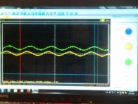
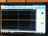
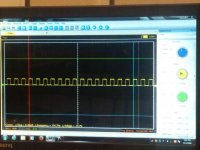
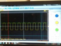
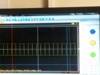
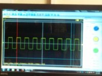
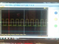
Scope setting is 10.0us / 50.0v
Pic1 is oscillation and positive rail
Pic2 is oscillation and negative rail
Pic3 oscillation and positive gate drive
Pic4 is oscillation and negative gate drive
Not sure what the gate drive signal on the outputs is supposed to look like but on the positive gate, the signal is exactly the same as on output leg3, while on the negative output gates, there is a much smaller waveform than the rail to rail waveform on the output leg2.
Attachments
Tested for audio on the relay input terminal and have clean audio again, maybe it was there all the time and I was just testing in the wrong location...
However, the relay is still not engaging. How do I figure out why?
However, the relay is still not engaging. How do I figure out why?
In the future, use alt-prt-sch to capture the scope image and then paste in a graphics program and save. That will give clear images.
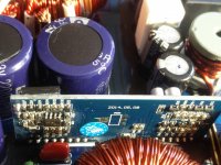
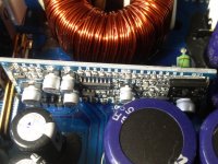
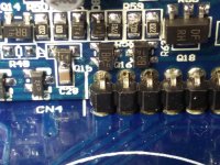
Post a photo of the component side of the power supply driver board.
Post a photo of the component side of the power supply driver board.
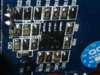
The power supply driver board has components on both sides. The 8pin op-amp component appears non-original to my untrained eye...
Attachments

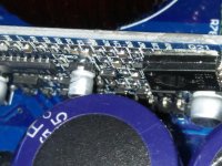
There is a solid 12v on one of the coil terminals, the other has only "bleed through" 12v due to the solid 12v on the other end. The other terminal goes to pin9(or pin6 depending on where you start) of the driver board. With a test light connected to ground, it does not light up on this terminal as it does on the other terminal. I was just a bit wary of testing the relay by connecting a ground to it for fear of damaging something. Currently trying to figure out where on the driver board it goes.
- Status
- Not open for further replies.
- Home
- General Interest
- Car Audio
- Crunch P3000.1D relay not engaging