Are you sure it's negative 15v and not -5v on pin 4 of the TL072?
The defaced IC is likely an LM211 and should have positive 5v on pin 8.
The defaced IC is likely an LM211 and should have positive 5v on pin 8.
Replaced the +5v regulator and now have +5v regulated voltage at ICs on the driver board. I resoldered pin6 on the IR21844 and now have +4.8v of gate drive on the negative outputs and +4.5v of gate drive on the positive outputs.
The relay is still not engaging so I haven't tested for output. What do I check next to determine why the relay is not engaging? Or should I jump pins 2-3 on the driver IC and test for output?
The relay is still not engaging so I haven't tested for output. What do I check next to determine why the relay is not engaging? Or should I jump pins 2-3 on the driver IC and test for output?
So I decided to test for audio. I connected the speaker - wire to the - speaker terminal and touched the + speaker wire directly to the relay terminal connected to the outputs. At first I got a funny noise so I quickly removed the wire and checked my incoming rca signal. Only one rca plug was working so I disconnected the other one and checked for audio again. This time there was clean bass when connecting the + speaker wire to the remote terminal.
I then decided to try jumping pin2 to pin3 on the output IC in order to test the relay. After making the connection I powered up but did not hear the relay engage. I removed the jumper from pin2 to pin3 and decided to test the audio again. This time there is a noise that sounds like a Star Wars weapon firing over and over again and the current limiting bulbs on my power connection start to glow. I think it was the same sound that I heard at first that went away but this time it is not going away, and I no longer have clean audio.
I need to figure out what happened to the clean audio, and also why the relay wasn't engaging.
Performed the test procedure on the IR21844 and all of the readings are similar to what they were before. The sound is like a laser/beep type of sound recurring with increasing frequency as the current draw increases. I have not left it long to hear or see what happens as I am fearful of doing more damage.
The output gate drive voltage drops from 4.8v to 2.3v on the negative outputs when the speaker + is touched to the relay input pad. The positive gate drive drops by half also as the noise emanates and increases in frequency.
If you jump 2-3 again, do you see a square wave equal to the sine wave frequency driven into the amp on the output of the LM211?
Will try with the scope shortly but with the voltmeter right now, if I jump pin2-pin3 the gate drive voltage disappears.
That's what you want. You need to check the signals up to the IC.
Do you have any 10k resistors? To better check the TL072, a 10k resistor connected between terminals 1 and 2 of the TL072 will allow you to see if the IC will pass clean audio at lower signal input levels.
Do you have any 10k resistors? To better check the TL072, a 10k resistor connected between terminals 1 and 2 of the TL072 will allow you to see if the IC will pass clean audio at lower signal input levels.
Pin2 jumped to Pin3 of the IR21844, 10k resistor connecting Pin1 to Pin2 of the TL072 on the driver board, and have no gate drive voltage on the outputs.
No audio output, no square wave on Pin7 of the LM211(defaced IC). I am posting a pic of the scope screen of Pin7 output with a 1khz signal input. Setting is 50.0ms/10v.div
The hurtful part is that I had clean, powerful bass output from the amp until I jumped pin2-pin3 of the IR21844. Hoping it is something simple...
Jumping pin 2-3 has never done any damage as far as I know. What can cause problems is soldering on the IC if the rail caps are charged.
Without the 5v regulator, I don't see how you could have had clean audio.
1k may not make it through the crossover. Use 50-100Hz.
As you increase the signal level, you should start to see clean audio on the output of the TL072 and a square wave on the output of the LM211. The square wave should swing ±5v.
On pin 1 of the 21844, you should have a drive signal with an amplitude of 10v that's referenced to the negative rail.
After I replaced the 5v regulator I had gate drive voltage on the outputs and when I tested for audio, it was playing clean and powerful but the relay was not engaging so I tested at the relay terminal. It was after attempting to jump Pin2 to Pin3 of the IR21844 that I lost audio. I honestly can't rule out soldering to the pins with rail caps charged as I was working on it all day.
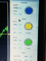
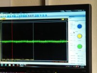
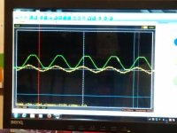
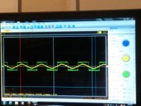
The following screen shots are with pin2 jumped to pin3 of the IR21844, with a 10k resistor soldered from Pin1 to Pin2 of the TL072, and a 100hz sine wave input into the amp. The setting for all of these was 5.0ms / 2.0v.
Pic 1 is scope settings
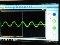
Pic 2 is 100hz input at rca connector
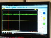
Pic 3 is pin1 of TL072 (or is pin7 the output to check?)
Pic 4 is pin7 of LM211(U3)
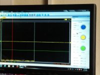
Pic 5 is Pin1 of IR21844
The following screen shots are with pin2 jumped to pin3 of the IR21844, with a 10k resistor soldered from Pin1 to Pin2 of the TL072, and a 100hz sine wave input into the amp. The setting for all of these was 5.0ms / 2.0v.
Pic 1 is scope settings
Pic 2 is 100hz input at rca connector
Pic 3 is pin1 of TL072 (or is pin7 the output to check?)
Pic 4 is pin7 of LM211(U3)
Pic 5 is Pin1 of IR21844
Attachments
Last edited:
There is a missing image. With no corresponding file name to pis#, I don't know which is missing.
Drive a stronger signal into the amp so that the output of the TL072 is just before it's clipping.
Drive a stronger signal into the amp so that the output of the TL072 is just before it's clipping.
Input is clipping. Had deck volume maxed out trying to get the TL072 close to clipping. Yes, have square wave from LM211 now.
Do you now have a square wave of about 10v, (referenced to the negative rail) on pin of the 21844?
Setting the gain higher, the crossover higher or the subsonic filter lower may have helped you to get a stronger signal at the TL072. For future reference.
Setting the gain higher, the crossover higher or the subsonic filter lower may have helped you to get a stronger signal at the TL072. For future reference.
- Status
- Not open for further replies.
- Home
- General Interest
- Car Audio
- Crunch P3000.1D relay not engaging