Got a Crunch P3000.1D here that powers up and has +/-54v of rail, but the output relay is not engaging and there is - 54v on the speaker + output trace going to the relay coming from the outputs.
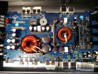
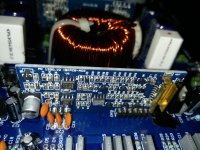
If I remove the 2 IRFP250 outputs connected to the negative rail, the voltage on the speaker trace goes away. The outputs are not defective as replacements do the same thing. I am not sure how to troubleshoot the driver board in this amp, nor the relay engagement circuit. Any advice would be appreciated. Pics of the complete board and the audio driver board are attached. Thanks.
If I remove the 2 IRFP250 outputs connected to the negative rail, the voltage on the speaker trace goes away. The outputs are not defective as replacements do the same thing. I am not sure how to troubleshoot the driver board in this amp, nor the relay engagement circuit. Any advice would be appreciated. Pics of the complete board and the audio driver board are attached. Thanks.
Attachments
On the driver IC, solder a bridge between legs 2 and 3. This will disable it.
What is the DC voltage on the output transistors measured with the black probe on the source and the red probe on the gate?
What is the DC voltage on the output transistors measured with the black probe on the source and the red probe on the gate?
Measured with black probe on source and red probe on gate:
Positive outputs - 107.7
Negative outputs +11.2
Will reserve bypassing the relay until afterwards...
Positive outputs - 107.7
Negative outputs +11.2
Will reserve bypassing the relay until afterwards...
Sorry, I probably did 1-2 for the positive outputs but the negative output reading is correct.
Positive outputs 0.00
Negative outputs 11.23
1-2 on the positive reads - 108 and 1-3 gives 0.00
1-2 on the negative reads the same as 1-3
Positive outputs 0.00
Negative outputs 11.23
1-2 on the positive reads - 108 and 1-3 gives 0.00
1-2 on the negative reads the same as 1-3
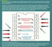
Measured the driver IC as indicated in the illustration:
1) 48Kohm
2) 50Kohm
3) 3.8Kohm
4) 68Kohm
5) 49Kohm
6) 2.19Mohm
This test was done with outputs still in the amp and the rail caps discharged. All four outputs measure exactly the same and are not likely shorted.
1) 48Kohm
2) 50Kohm
3) 3.8Kohm
4) 68Kohm
5) 49Kohm
6) 2.19Mohm
This test was done with outputs still in the amp and the rail caps discharged. All four outputs measure exactly the same and are not likely shorted.
According to the attachment, it states that a reading below 10K ohms indicates a likely damaged IR21844. Does the 3.8k ohm reading of test 3 (pins5-7) mean that the IC is defective?
Is there anything else I can check in the meantime since I have to order that IC?
Is there anything else I can check in the meantime since I have to order that IC?
It's questionable but that is also connected across the ceramic filter capacitor and the 12v regulator. Desolder and lift pin 7 then re-check test 3.
Pin 7 of the IR21844 IC? I am likely going to end up destroying it in the process. Can I remove the next component in the circuit with pin 7 and test from there?
I lifted pin7 and performed the test again.
1) 50Kohm
2) 439Kohm
3) 779Kohm
4) 460Kohm
5) 50Kohm
6) 2Mohm
1) 50Kohm
2) 439Kohm
3) 779Kohm
4) 460Kohm
5) 50Kohm
6) 2Mohm
Considering that there is no reading taken that is below 10K ohms form the IR21844 with pin 7 lifted, and that the 3.8k ohms reading from testing with pin7 connected to its pad, does this mean that the IR21844 is not likely defective?
If so, what can I check next?
If so, what can I check next?
The IC generally leaks or shorts when it drives an output terminal when it's disabled but there may be other failure modes.
Do the low-side FETs have any drive voltage (1-3) if you lift pin 6 of the driver IC?
Do the low-side FETs have any drive voltage (1-3) if you lift pin 6 of the driver IC?
Check for drive at the FETs with pin 6 and 7 disconnected.
Check for 12v on pad 7, Black probe on pin 5.
Solder pin 7 back down and re-check for 12v on 5/7.
Check for 12v on pad 7, Black probe on pin 5.
Solder pin 7 back down and re-check for 12v on 5/7.
See also post #18.
While you're checking, confirm that all low voltage supplies are OK (±5 on the TL072 on the driver board and ±15v on the preamp op-amps.
While you're checking, confirm that all low voltage supplies are OK (±5 on the TL072 on the driver board and ±15v on the preamp op-amps.
With pin6 and pin7 lifted there is no drive voltage at the outputs measuring (red 1-3 black)
Black probe on Pin5, there is 12.2v on pad7
With pin7 soldered down, there is 12.2v on pin7 when measured (black 5-7 red)
Pin7 soldered down and pin6 lifted, black probe on Pin5 there is 11.5v on lifted pin6, and 0v on pad6
All opamps in preamp section have +/-15v
TL072 on the driver board has - 15v but - 0.7v on pin8. There is another 8pin op amp on the board which is defaced and has - 15v and - 0.7v on pin8 also.
- Status
- Not open for further replies.
- Home
- General Interest
- Car Audio
- Crunch P3000.1D relay not engaging