What have you got on the 739 or 749? TO5 metal cans with 10 radial leads? If it is DIP package, plastic and ceramic packages used to have the same pinouts.purchased a new/old ceramic package ua739. $12.00 delivered. From Ca. will be awhile before I can test it. Who wants to take odds on the difference in the opamp outputs?
Good luck on a datasheet showing different package pinouts. I always start looking at datasheetcatalog.com, although some obsolete stuff they don't have. If you get really stuck, I might have an old fairchild IC databook in the attic someplace. Although I haven't seen it in the last couple of years.
I think since I don't need hydraulic valve or other actuator DC control, only loud music, I would have bought some LME49810 audio junction transistor drivers at $5.60 each and been done with it. Plus some $3 big insulators and some sort of aluminum heat sink (junk probably, I use door channel as TO220 heat sinks).
I think before I spent $12 on one IC I would have tested the amp on music. For a source I use a pocket radio I fished out of the trash after a locker cleanout, and replaced the garbage volume control with a fixed resistor. It has fixed volume now. It takes a 1/8 stereo plug to dual 1/4 phone plug convertor to drive both channels of my PA amp. Actually 3 converters, and I had to buy them.
If you put the radio on a rock station, you can tell by the movement of the pointer on the AC scale of an analog voltmeter (NOT a DVM, they average over 4 seconds), that the music is getting past point X. Large steady AC voltages with no beat are suspicious as RF oscillations.
Last edited:
the existing opamp is a ua739 molded dip, the new is ceramic dip.
I have listened to the reworked channel several times...low volume...using 2 way BIC speaker. Sounded fine. Have not listened to both channels at the same time. Nor with any amount of juice.
My plans were to rebuild the operating channel channel 2 using the same transistors used on channel 1. Both would then be matched.
After all work is completed...satisfied with sound...run resistor load on both channels...3/4 gain for a 12-24 hr period? just to weed out compromised parts or infant mortality?
Great, I'm glad one channel is sounding properly. Ceramic dip is the high temperature version of the plastic dip package, usually.
Well, high wattage test as long as you can stand to watch it. I've got 2 each 5 ohm resistors in series as a load, and a $2 4 ohm impedance speaker series back to back electrolytics across one of the fives, to listen to it while I heat it up. If something lets go it tends to pop and sound funny. I calculate wattage P=(V^2)/R. I measure the V with my VOM, that is why I bought the 8 ohm resistors back when. The ST70 tube amp tends to lose power supply rail voltage, and power due to caps and tired tubes, in a few short years. Transistor amps are more digital in the failure modes, unfortunately.
I've got another blister pack of 5 ohm $5 resistors to parallel some and make a 900 watt load to test my PV-1.3k at four (five) ohms and 650 watts. But I need to build a working DC protection circuit, first. I have a design, but stuffing it in without tin connectors at low voltage and current (unreliable by design) is a challenge.
Last edited:
glad I didn't take bets on the new ceramic chip. No considerable improvement In the outputs. Will be replacing c4 today.
You've got the 739, which makes the amp repairable into the 21 st century. WIthout it you had a case with a heat sink and fan if one blew. The price tells me they are quite weird. datasheetcatalog bangs off into hundreds of 1nx739 zener diodes instead of pulling up the file on the op amp.
Indianajo, thanks for the schooling on debugging these, great methodology; getting ready to tackle one myself.
Don't forget DJK. That one pair of output transistors class AB, the other 4 pairs class B only is quite weird and something I've never seen before. DJK's advice that the amp won't work properly with a lightbulb in the AC line was news to me, too. Without, use safety glasses at turnon, I blew the die through a couple steel transistor tops before I found something between the 60 W bulb I had and the unlimited wall voltage. (100 w bulbs were banned from sale at the time).
Indianajo's Peavey CS800S is another, no current thru the outputs at idle is what DJK is referring to? BGW is another.
Craig
Craig
The drivers in the Crown provide up to about 120mA directly to the speaker before the outputs start to conduct.
The negative driver drops from AB into B (shuts off) at about 240mA peak current, or about 1/4W into 8Ω.
So the output is class AB to 1/4W and then above there the outputs move into class B.
The negative driver drops from AB into B (shuts off) at about 240mA peak current, or about 1/4W into 8Ω.
So the output is class AB to 1/4W and then above there the outputs move into class B.
Replaced C4 no change in outputs from opamp.
I do know that replacing the zener on the +10V increased the +10V from 9.3 to 9.5 and increased the opamp outputs from -.5V to -.3V.
The zener installed was tested on the bench and measured 9.95V.
Should I try to get the +10V closer than +9.5V?
I do know that replacing the zener on the +10V increased the +10V from 9.3 to 9.5 and increased the opamp outputs from -.5V to -.3V.
The zener installed was tested on the bench and measured 9.95V.
Should I try to get the +10V closer than +9.5V?
It is within tolerance for a B suffix part. I wouldn't worry about that. Do you still have DC offset on the repaired output with no input? That can't be corrected by the potentiometer?
amp is able to have DC offset set to 0V. Indianajo I forwarded the UA739 datasheet via email.
time permitting I will start taking measurements looking for components that do not seem to measure correctly.
I started playing with a Philco 38-12 vacuum tube radio.
time permitting I will start taking measurements looking for components that do not seem to measure correctly.
I started playing with a Philco 38-12 vacuum tube radio.
what is it doing that warrants replacement?
I purchased a replacement off of Ebay. It was a ceramic package. The issue I am having with the output being low was not the chips fault. No change in the output. I actually wasn't surprised because the output was low on both sides.....have not gotten back to it...but will.
I purchased a replacement off of Ebay. It was a ceramic package. The issue I am having with the output being low was not the chips fault. No change in the output. I actually wasn't surprised because the output was low on both sides.....have not gotten back to it...but will.
One channel is stuck at +60V. The chip is getting a signal to correct that but its output isn't doing what it's supposed to do. Either the chip is bad or something is pinning its output. I replaced the 2N4125 but that didn't fix anything.
You want to sell your extra one?
You want to sell your extra one?
And if the output is low on both channels, I suspect the boost voltage, sometimes called the voltage doubler. There is a little circuit with a couple of diodes, a couple of capacitors, and a zener that supplies a boost voltage to both channels. The capacitors usually fail from age. I believe the 10 microfarad 160 V unit is often the culprit.
Measure that zener and if it's not working, that's likely the problem.
Measure that zener and if it's not working, that's likely the problem.
I didn't read all the previous messages so I guess my reply was redundant. The zener does not have to be precise; it's in there to prevent wild variations of the boost voltage.
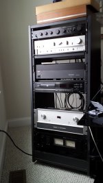
anatech just connected up with me on my initial plea for help. Reminded me that I never really showed the finish product. It has been awhile since I rebuilt channel 2, about three months back or so. This involved replacing all outputs and drivers along with matching the predrivers replaced on the main board. These were all required to get channel 1 operating. Replaced the pots with new ones. Fab.d the missing rack flanges and reassembled and tested. Finally made it upstairs out of the basement hooked in to the main system. Bought a used rack and assembled some of the stuff into it. This amp is a beast as far as power and runs incredibly cool even when running it a bit loud.
actually the photo doesn't show the Furman power conditioner that my brother got for my birthday. It has the pull out LED's, nice for using the rack at night.
actually the photo doesn't show the Furman power conditioner that my brother got for my birthday. It has the pull out LED's, nice for using the rack at night.
Attachments
Last edited:
- Status
- Not open for further replies.
- Home
- Amplifiers
- Solid State
- Crown DC300A Repair/Restore