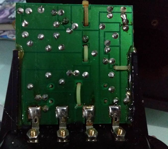
Those 4 push on tabs at the bottom of the XO board in the top pic look like they could use a cleaning.
Now that I have opened up the speaker can I just switch the connectors at the tweeter without doing anything to the crossover ? I am just afraid that the capacitor might be polarised one. Coz i have had bad experience with exploding polarized capacitors when i wired them wrongly.
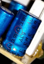
Pretty shure marked symbolize "Non polar". Cant you just measure woofer alone then without touching any settings else than disconnect woofer and connect tweeter measure again, then use the "All SPL" or "Overlays" windows into REW to show how they integrate SPL wise. If tweeter is way apart SPL wise from woofer then R1 and or R2 could have drifted to higher values because of overload or other reason.
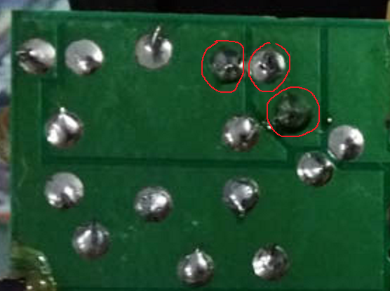
Marked ones don't look as nice floating as the other solder joints and maybe have sign of black oxidation around the leads, the three joints belong to R2 and hot wire for tweeter. On the other hand if the other speaker has same response they probably fine then.
Attachments

Last edited:
Pretty shure marked symbolize "Non polar". Cant you just measure woofer alone then without touching any settings else than disconnect woofer and connect tweeter measure again, then use the "All SPL" or "Overlays" windows into REW to show how they integrate SPL wise. If tweeter is way apart SPL wise from woofer then R1 and or R2 could have drifted to higher values because of overload or other reason.

Marked ones don't look as nice floating as the other solder joints and maybe have sign of black oxidation around the leads, the three joints belong to R2 and hot wire for tweeter. On the other hand if the other speaker has same response they probably fine then.
Thanks Brytt for the suggestion. When u said to measure woofer alone, did u mean to measure only the woofer without the crossover and likewise for the tweeter ?
Thanks Brytt for the suggestion. When u said to measure woofer alone, did u mean to measure only the woofer without the crossover and likewise for the tweeter ?
Think best with XO in the chain especially to not overload tweeters coil. So scenario something ala this, mic 1m on axis tweeter, start measure woofer and find amp levels that suit mic sensitivity and REW, speaker cable from amp only connected to woofer terminals on XO, thereafter repeat for tweeter measurements but don't touch any settings or positions on mic and speaker box, only thing to do before measure tweeter is move speaker cable from woofer terminals to tweeter terminals on XO, okay suggest turn off amp when changing speaker cable terminals on XO but don't touch volume level on amp : )
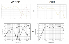
Ideal those two measurements into "All SPL" or "Overlays" windows in REW should show something ala the "stereophile" measurement below. That probably would not happen but gets us closer to what then to do, think most would expect tweeter to be ducked several dBs below woofer output if its even saying anything at all. If that is the outcome a DMM (Digital multi meter) would be handy to measure R1/R2 values and RE of tweeters coil.
Attachments

Hi Buzzy,
Please excuse me if this is a dumb question but are you powering the ECM8000 with a 48V phantom supply?
Peter
Please excuse me if this is a dumb question but are you powering the ECM8000 with a 48V phantom supply?
Peter
Hi Buzzy,
Please excuse me if this is a dumb question but are you powering the ECM8000 with a 48V phantom supply?
Peter
Post 10 quoted below suggest there is hope 🙂
.....I have tested another brand speaker (much cheaper) that I have and it measures fine without the huge dip in high frequency response like this.
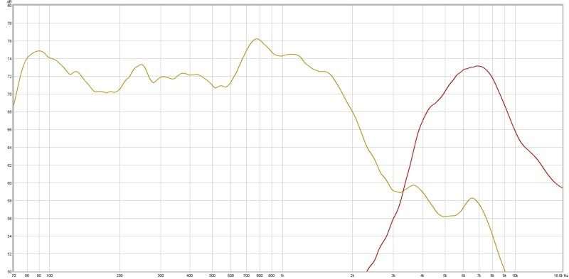
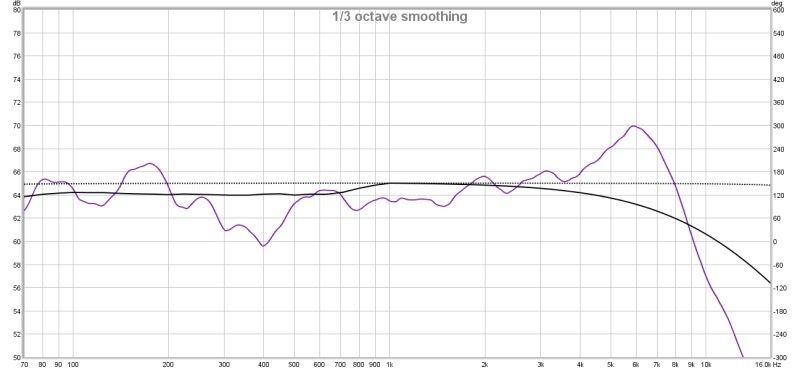
I tested the speakers as Brytt had suggested and this was the result. Pls ignore freq beyond 6Khz. Did not move mic position and volume was at same level for both tweeter and woofer test. Mic on axis at 1m from speaker.
I tested the speakers as Brytt had suggested and this was the result. Pls ignore freq beyond 6Khz. Did not move mic position and volume was at same level for both tweeter and woofer test. Mic on axis at 1m from speaker.
where are you measuring these ? inside or outside ?
If inside, take the speaker outside and put it up on a stool ( on the edge of the stool too )
Like this, But move the mic closer to speaker.. 🙂

where are you measuring these ? inside or outside ?
If inside, take the speaker outside and put it up on a stool ( on the edge of the stool too )
Like this, But move the mic closer to speaker.. 🙂
In the living room. Outside is impossible. I live in an apartment that is close to expressway. Do u think measuring inside the living room causes the huge dip at abt 3khz ? The other brand speaker i measured does not have this dip.
I tested the speakers as Brytt had suggested and this was the result. Pls ignore freq beyond 6Khz. Did not move mic position and volume was at same level for both tweeter and woofer test. Mic on axis at 1m from speaker.
The tweeter response between 3KHz crossover point to 7KHz looks very strange. Do both tweeter measured the same? If yes, it may be your room.
If the two speakers look different, it could be defect in one of the tweeters or in crossover components
The later can be trouble shoot with a dummy resistor load replacing the speaker drivers. It will help you find the defective parts, but not fine tuning the crossover design.
I tested the speakers as Brytt had suggested and this was the result. Pls ignore freq beyond 6Khz. Did not move mic position and volume was at same level for both tweeter and woofer test. Mic on axis at 1m from speaker.
Those slopes doesn't look as ones that would sum flat but at least we see there is output from tweeter. To get less room and more direct sound you could try same measurement again with mic at 0,5 m distance and post the result if it show other result than above.
Why should we ignore frq beyond 6kHz is mic defect or what, also can you confirm its Mission m71 model which is supposed to have XO point at 2,8kHz.
To rule out any components in the chain is not responsible any flaws would be nice see another speaker full range or multi way measured within exactly the same setup, and that of course should show no 3kHz lack.
The tweeter response between 3KHz crossover point to 7KHz looks very strange. Do both tweeter measured the same? If yes, it may be your room.
If the two speakers look different, it could be defect in one of the tweeters or in crossover components
The later can be trouble shoot with a dummy resistor load replacing the speaker drivers. It will help you find the defective parts, but not fine tuning the crossover design.
Both the mission speakers have almost the same freq response with the huge dip at around 3Khz. Manufacturer crossover freq is claimed to be 2.8Khz.
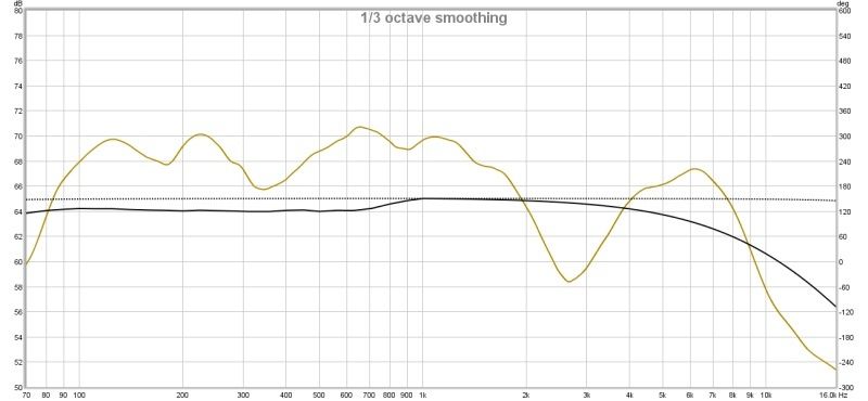
I have tested another brand speaker in the living room at the exact same spot where I measured the mission speaker and this is what I got.
To see if the room is causing the dip I placed the mission speaker in another room and this is what I get. So with this can i rule out that the room is causing the dip in frequency response ?
Now that I have opened up the speaker can I just switch the connectors at the tweeter without doing anything to the crossover ?
Yes, that's what I would do.
Those slopes doesn't look as ones that would sum flat but at least we see there is output from tweeter. To get less room and more direct sound you could try same measurement again with mic at 0,5 m distance and post the result if it show other result than above.
Why should we ignore frq beyond 6kHz is mic defect or what, also can you confirm its Mission m71 model which is supposed to have XO point at 2,8kHz.
To rule out any components in the chain is not responsible any flaws would be nice see another speaker full range or multi way measured within exactly the same setup, and that of course should show no 3kHz lack.
The mic belongs to a friend and he told me that the mic is not responsive above 6Khz. I just asked him about this and he replied that he had replaced the mic capsule in the ECM8000 mic. He has access to a calibrated earthworks reference mic in the lab of our college which he calibrated this mic capsule with.
I measured the both the resistors R1 and R2. Only R2 is off from labelled value of 1.6 ohm.
R1=1.8 ohm
R2=1.4 ohm
Last edited:
The blue cap should be non-polar (bi-polar).
The woofer circuit looks like 2nd order with some response, correction and shaping sub-circuits. Tweeter circuit is 3rd order. If either of those resistors is dead, then that would give the bad HF response in your test.
I have all the while been thinking that both the tweeter and woofer circuits have to be of the same order. I have been looking up crossover circuits and I still can't figure out that the woofer is 2nd order. I can see that the tweeter looks like a 3rd order like u said. But it has alot of capacitors. Capacitors in parallel add up in value. In that case can I assume that the manufacturer tried to make up for a capacitor value not available in a single package ?
Buzzy the SPL levels shown in the graph are too far down in level to inspire confidence in your methodology.Double check to see that you are supplying a level of one watt to the speaker under test and that a series resistance is not fitted between the amplifier and the speaker. If you can get hold of another calibrated microphone with a known sensitivity,use this and make sure this figure is inserted into the mic. sensitivity file.
Do u mean to say that 70db is not enough ? But higher volume levels still provide the same frequency response graphs. I will google how to supply 1 watt of power and try again.
The SPL is calibrated against a known standard i.e. a calibrated microphone or SPL meter. A reasonably high level is needed to overcome background noise and the one watt input level is a universally accepted standard,as is the one meter on axis position for the measuring microphone.If you do not have a Vac measurement facility on your computer program then you will need a DMM with a wide freq. response range and a calibration resistor.
I have all the while been thinking that both the tweeter and woofer circuits have to be of the same order. I have been looking up crossover circuits and I still can't figure out that the woofer is 2nd order. I can see that the tweeter looks like a 3rd order like u said. But it has alot of capacitors. Capacitors in parallel add up in value. In that case can I assume that the manufacturer tried to make up for a capacitor value not available in a single package ?
Beside the electric XO will form a certain measured slope the measured inherent acoustic fall off for the drivers at design axis should be added to the electric slope and that brutto sum is the real slope. Beside that unsymmetrical slopes or XO points can be used to correct for at design axis that ones ears hasn't exactly same distance to voice coil of tweeter verse woofer (acoustic center). Therefor don't think we have to worry about how the electric schematic looks like compared to textbook circuits.
At moment think the concern is if we can trust your microphone is precise up to 6kHz, and if it is precise then electric XO must have errors because your measured slopes ain't gonna sum flat in they seems spaced apart being > -12db down at XO point. A few comments is that a 0,1 ohm error on R1 or R2 is so little it ain't gonna change anything as much as we want changed here and if either tweeter or woofer ab fabric had by accident their wires reversed feeding driver with wrong polarity that was planned from designer either seems not enough to get flat response.
Below is your measurements verse "sterophile" measurements Mission m71 loudspeaker Measurements | Stereophile.com. You could try reverse wire terminals on woofer or tweeter driver then measure them summed again but don't think it will do it. My speculation is do the best you can to find a partner with a microphone you can borrow or take yours to his place to see if they measure equal the same, and after that we can claim XO/wire ring/drivers malfunction or not.
Attachments
Last edited:
- Status
- Not open for further replies.
- Home
- Loudspeakers
- Multi-Way
- Crossover tuning