You could also remove the jumpers and connect the tweeter -ve to the woofer +ve (and vice versa with jumper wires to test whether inverting the phase fixes the issue!
The metal jumpers (arrowed) MUST be removed. Also as a santity check I'd make sure that with the jumpers removed that there is no continuity between the HF and LF +ve terminals, and similary with the -ve terminals. Any short will likely blow the output stage of your amp.
Certainly it looks like the speakers were configured to be able to be bi-wired.
Tony.
Thanks for this suggestion. I did it this way and checked for continuity with multimeter between the HF and LF +ve terminals. They are shorted out. I had removed the copper jumpers as u suggested. I think i have no choice but to open up the speaker.
So possibly the terminals are just cosmetically biwired?!!
I will be opening it later and that should answer some of the questions. I tried connecting just HF terminals to see if tweeter was working. It had sound coming through but at a low level. Is this normal ?
Last edited:
Sound from tweeter will be quiet compared to woofer. But I don't understand how there can be a short HF+ to LF+ if properly biwired.
There shouldn't be!! But if the tweeter is incorrectly wired, then perhaps some other errors, hence the check 🙂 Just don't want to suggest something that results in a blown up amplifier!
Tony.
Tony.
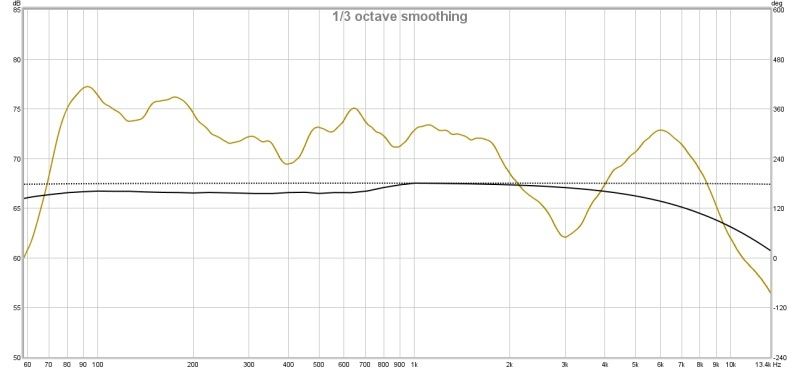
From that measurement in the original post were not just looking at a reverse polarity connection there is a complete lack of high frequency energy. If all of the hardware was operating properly I'd have assumed this was near field with the mic on axis with the woofer.
If this is 1 meter away on the tweeter axis then something really isn't right. If the tweeter are working properly then there is definitely wrong with the hardware set up or software settings.
If this is 1 meter away on the tweeter axis then something really isn't right. If the tweeter are working properly then there is definitely wrong with the hardware set up or software settings.
There shouldn't be!! But if the tweeter is incorrectly wired, then perhaps some other errors, hence the check 🙂 Just don't want to suggest something that results in a blown up amplifier!
Tony.
This is how i wired the jumper wires.

With a multimeter I tested both the red HF and LF terminals. Continuity test shows that they are connected and has a 4 ohm resistance. The same is true for the black HF and LF terminals. Now I am just scratching my head as to what I have done wrong. Continuity testing all the terminals shows that each and everyone of it is connected to each other.
I made another test without the speaker grille on. The mic is on axis with tweeter and placed 2m away.
This is how i wired the jumper wires.
An externally hosted image should be here but it was not working when we last tested it.
With a multimeter I tested both the red HF and LF terminals. Continuity test shows that they are connected and has a 4 ohm resistance. The same is true for the black HF and LF terminals. Now I am just scratching my head as to what I have done wrong. Continuity testing all the terminals shows that each and everyone of it is connected to each other.
how come you reversed the polarity on the woofer too ?
try this,
positive to positive ( woofer )
Negative to Negative ( woofer )
Positive to Negative ( tweeter )
Negative to Positive ( tweeter )
No measure 🙂
Since you are already using REW, try measuring the impedance of the speaker system using an impedance zig. This will probably throw more information about the crossover too for any wrong component insertioWiring etc. Also the impedance phase can reveal lot of information.
I believe thats how its wired in the pic zeeup. The white wire is positive and it goes to the positive woofer thru the blue jumper cable. The black wire is the negative and it goes to negative woofer terminal thru the green jumper cable.
I believe thats how its wired in the pic zeeup. The white wire is positive and it goes to the positive woofer thru the blue jumper cable. The black wire is the negative and it goes to negative woofer terminal thru the green jumper cable.
sorry my bad, hard to understand how they wired and placed them terminals.
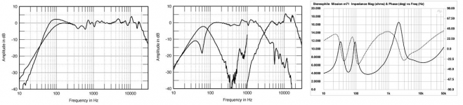
The speaker appears to be the Mission M71 model and this is stated to have an average sensitivity of 88db for one watt at one meter.If your mic measurement is accurate then there is a problem with the speakers which could be caused by incorrect xover wiring or a faulty component.An impedance curve is often useful in cases like this as it can show up failures such as shorted turns in a voice coil that a visual inspection could miss.
If it hold M71 is the model here link to "stereophile" review and measurement Mission m71 loudspeaker Measurements | Stereophile.com.
Honestly bit curious what's the cause
 .
.Attachments
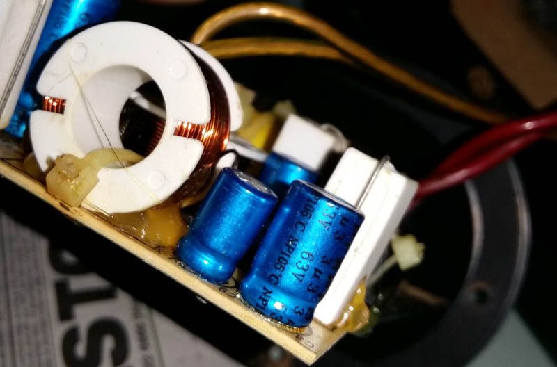
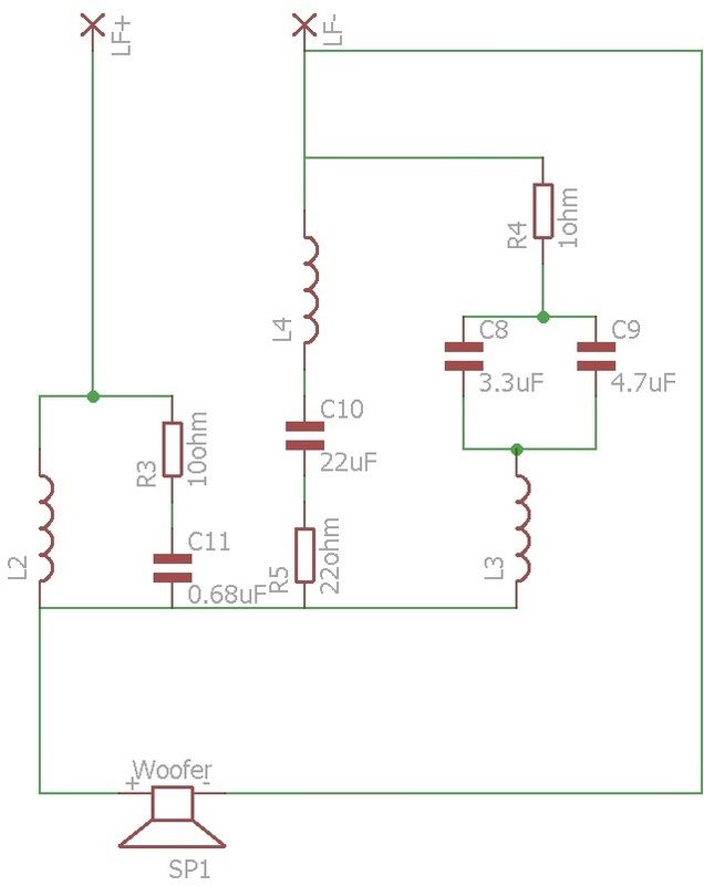
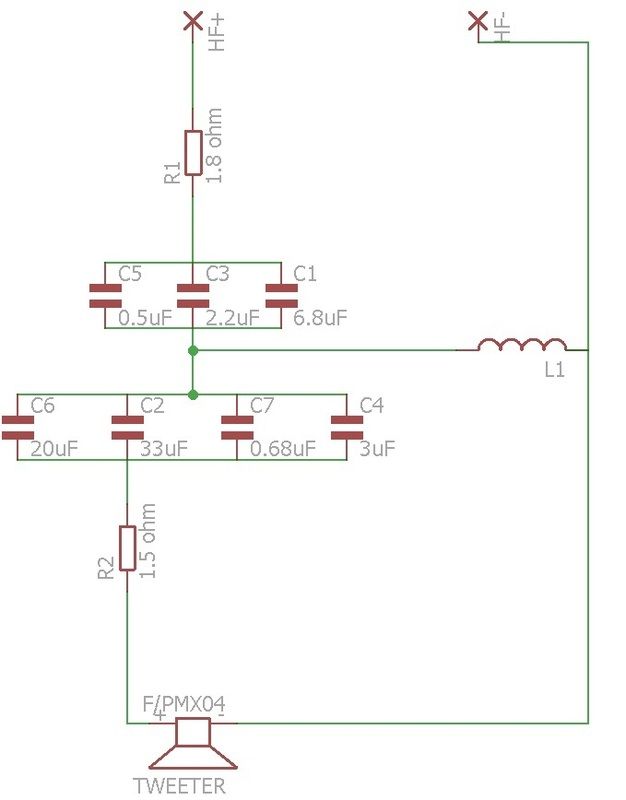
I have opened up the speaker to take a look at the crossover. I have also tried tracing the parts to make an initial sketch of the schematic. Those blue capacitors in the pictures are they polarized electrolytic capacitors ? I modelled all the caps as bipolar. My electronics knowledge is kinda of rusty and had to use google to decode those values. I can't find out the values for all of the inductors.

Last edited:
The blue cap should be non-polar (bi-polar).
The woofer circuit looks like 2nd order with some response, correction and shaping sub-circuits. Tweeter circuit is 3rd order. If either of those resistors is dead, then that would give the bad HF response in your test.
The woofer circuit looks like 2nd order with some response, correction and shaping sub-circuits. Tweeter circuit is 3rd order. If either of those resistors is dead, then that would give the bad HF response in your test.
The blue cap should be non-polar (bi-polar).
The woofer circuit looks like 2nd order with some response, correction and shaping sub-circuits. Tweeter circuit is 3rd order. If either of those resistors is dead, then that would give the bad HF response in your test.
Or a bad solder looking at the dry board with rust..
Or a bad solder looking at the dry board with rust..
I think my camera is not good enough. That rust like thing u see is actually wood dust from the cabinet. Must have gotten there when i was unscrewing it.
Now that I have opened up the speaker can I just switch the connectors at the tweeter without doing anything to the crossover ? I am just afraid that the capacitor might be polarised one. Coz i have had bad experience with exploding polarized capacitors when i wired them wrongly.
Speaker crossovers are an AC circuit. AC requires bi-polar caps. It is possible to use polarized caps, but they would have to be wired back to back in series to allow AC thru.
I think my camera is not good enough. That rust like thing u see is actually wood dust from the cabinet. Must have gotten there when i was unscrewing it.
i was referring to the oxidation on the leads of the resistors 🙂
Have you looked at the back side of the board to see if any loose solder joints ?
- Status
- Not open for further replies.
- Home
- Loudspeakers
- Multi-Way
- Crossover tuning